


 Home /
 Custom Battery Pack for Veterinary Medical Equipment: OEM Solution Guide


Table of Contents
- Why Veterinary Equipment Often Needs a Custom Battery Pack
- Defining Your Veterinary Battery Requirements
- Choosing the Right Cell Chemistry and Format
- BMS, Protection, and the Difference Between PCM and Smart BMS
- Mechanical and Thermal Integration for Veterinary Equipment
- From Prototype to Production: The OEM Battery Development Process
- Certification, Transport, and Documentation: What Evidence to Request
- How to Evaluate a Custom Battery Pack Supplier
- Getting Started with a Custom Veterinary Battery Pack
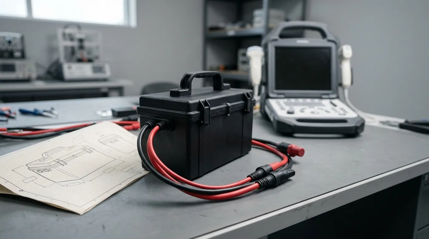
A custom battery pack for veterinary medical equipment is an application-specific rechargeable power source engineered around the device's voltage requirements, runtime target, current profile, physical enclosure, charging method, and the safety or transport documentation the OEM must supply with the finished product. This guide explains how veterinary equipment manufacturers define those requirements, evaluate chemistry and pack architecture options, and source a custom battery pack from an OEM supplier with the evidence needed for validation and worldwide shipment.
Veterinary equipment presents battery challenges that consumer devices rarely create. Portable ultrasound units, patient monitors, infusion pumps, anesthesia machines, dental tools, and mobile imaging systems each place different demands on their power source—and those demands change depending on whether the equipment moves between exam rooms, travels in a field vehicle, or remains on a treatment cart. For a deeper look at how battery packs are built around broader medical device requirements, see our medical device battery pack solutions overview.
Why Veterinary Equipment Often Needs a Custom Battery Pack
Standard commercial battery packs are designed for consumer electronics with predictable voltage rails, moderate current draw, and benign operating environments. Veterinary equipment rarely fits that pattern.
A portable ultrasound scanner may need a high startup current for its display and probe electronics, then settle into a moderate continuous load during an exam. A patient monitor may run for hours at a steady draw with occasional spikes when alarms trigger. An infusion pump requires consistent, controlled current to drive its motor accurately. Dental equipment can subject its battery to vibration and high peak loads. Mobile imaging systems may demand substantial energy in short bursts, then sit idle between procedures.
The physical environment matters just as much. Veterinary equipment is handled by multiple staff members, transported between locations, exposed to cleaning agents and disinfectants, and sometimes operated in uncontrolled temperatures. A battery pack designed for a consumer device may not tolerate those conditions—or may not physically fit the equipment's enclosure at all.
Runtime expectations also differ. A veterinary practice may need a monitor to run through an entire surgical procedure without recharging. A field clinician may need a diagnostic device to last through a full day of calls. These requirements drive the pack's energy capacity, which in turn affects cell selection, pack size, weight, and charging strategy.
Veterinary Equipment Categories and Their Battery Demands
| Equipment Category | Typical Load Pattern | Key Battery Considerations |
|---|---|---|
| Portable ultrasound / diagnostic imaging | Moderate continuous load with high startup peaks | Peak current capability, compact size, energy density |
| Patient monitors | Long-duration moderate load | Runtime, consistent voltage, reliability |
| Infusion / syringe pumps | Steady motor-driven load | Stable current delivery, predictable discharge |
| Anesthesia machines / mobile carts | Multiple subsystems, higher total energy | Total energy (Wh), larger pack size, thermal management |
| Dental equipment | High motor loads with vibration | Peak current, mechanical robustness, connector integrity |
| Mobile treatment / field equipment | Variable load, environmental exposure | Temperature tolerance, sealed enclosure, serviceability |
The table above shows general patterns, not universal specifications. Every device must be evaluated individually because two devices in the same category can have completely different voltage requirements, current profiles, and mechanical constraints.
Defining Your Veterinary Battery Requirements
Before contacting a battery supplier, define the requirements your device places on its power source. A complete requirements brief helps the supplier engineer a pack that fits your device—not just one that physically connects to it.
| Requirement Area | Information to Define |
|---|---|
| Electrical | Nominal voltage, maximum charge voltage, capacity (mAh or Ah), energy (Wh), continuous current, peak current and duration, accepted voltage sag |
| Mechanical | Available space envelope, connector type and location, wire length, mounting method, weight limit, serviceability (replaceable vs sealed) |
| Environmental | Operating and storage temperature range, humidity, cleaning or liquid exposure, vibration and shock, field handling |
| Charging | Charger voltage and current, CC/CV profile, target charge time, charging temperature range, communication requirements |
| Runtime | Load condition used for runtime—continuous, cyclic, or standby—and the duration required |
| Safety and market | Target markets, required documentation, safety test expectations, transport requirements |
| Lifecycle | Expected cycle life, replacement strategy, service life of the device |
The most common mistake OEMs make is specifying only voltage and capacity. Voltage tells the supplier which cell configuration to use; capacity in Ah describes charge quantity but not usable energy. Energy, measured in watt-hours (Wh), accounts for voltage and gives a more meaningful basis for runtime comparison. Likewise, continuous current and peak current are different requirements—a motor-driven pump may draw 2 A continuously but require 8 A for half a second during startup. The supplier must know both values to select appropriate cells and set correct BMS protection thresholds.
Runtime should always be defined against a stated load. A monitor that draws 1.5 A continuously from a 7.4 V pack needs more energy than one that draws 1.5 A intermittently. State the load profile explicitly in your requirements document.
Choosing the Right Cell Chemistry and Format
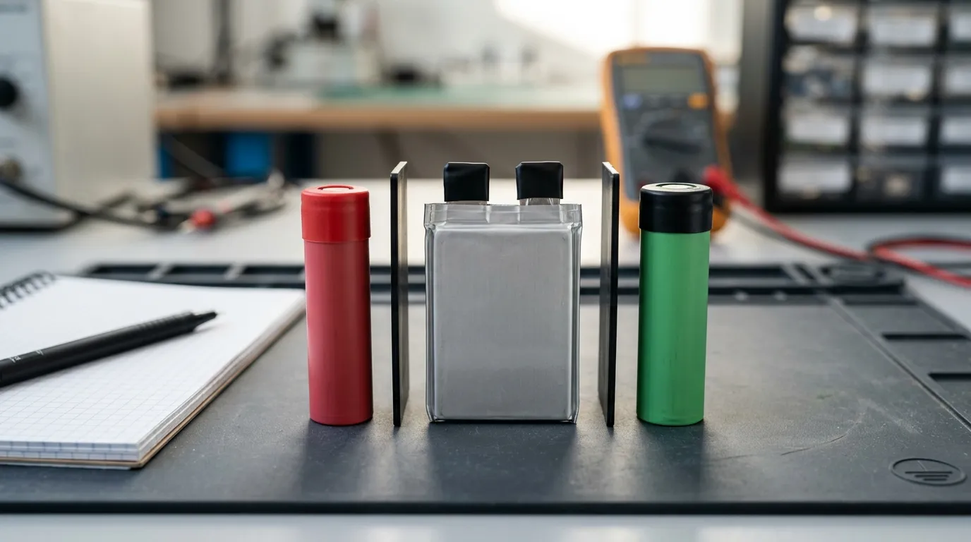
Cell chemistry determines the pack's nominal voltage, energy density, cycle life, temperature behaviour, and cost. There is no universally "safest" or "best" chemistry—the right choice depends on your device's requirements and the trade-offs you are willing to accept.
| Chemistry | Typical Nominal Voltage | Energy Density | Form Factors | Typical Strengths | Typical Trade-offs |
|---|---|---|---|---|---|
| Li-ion (lithium-ion) | 3.6–3.7 V per cell | High | Cylindrical, prismatic, pouch | Mature supply chain, good energy density, wide selection | Requires proper charging and protection; performance varies by cell grade |
| LiPo / lithium-polymer | 3.7 V per cell | High | Pouch / flat | Thin and flexible form factors, custom shapes possible | Requires mechanical protection; swelling behaviour must be designed for |
| LiFePO4 / LFP | 3.2 V per cell | Moderate | Cylindrical, prismatic, pouch | Long cycle life, stable voltage, lower thermal runaway risk | Lower energy density, different nominal voltage, larger pack for same energy |
Gloflux lists cylindrical, prismatic, and LiPo configurations within its medical device battery solutions, which means the practical range of form factors is broad for custom pack development.
Cylindrical vs. Pouch Cells
Cylindrical cells (such as 18650 or 21700 formats) are widely used in custom packs because they are robust, readily available, and perform well under mechanical and thermal stress. They are easier to mount and replace in serviceable packs, and they offer predictable thermal behaviour in multi-cell configurations.
Pouch cells offer more design freedom because they can be made thinner and shaped around the device's internal space. However, they require careful mechanical protection—pouch cells can swell with age or under fault conditions, so the enclosure must allow for some expansion without transmitting stress to other components.
The choice between cylindrical and pouch is driven by the device's physical constraints and service requirements, not by chemistry alone.
Understanding Series and Parallel Configurations
A battery pack's voltage is determined by how many cells are connected in series. Each series step adds the nominal voltage of one cell. A 3S configuration using 3.7 V Li-ion cells produces a nominal pack voltage of approximately 11.1 V. The total voltage must match your device's power architecture, not just be "close enough."
Parallel connections increase the pack's capacity and current capability. A 2P configuration doubles the capacity of a single string, meaning the pack can deliver a given current for twice as long—or deliver twice the current for the same duration, subject to cell limits.
| Configuration | What It Determines | Example |
|---|---|---|
| Series count (S) | Pack voltage | 3S Li-ion ≈ 11.1 V nominal |
| Parallel count (P) | Capacity and current capability | 2P doubles capacity of a single string |
Cell ratings should never be treated as pack ratings. A cell rated for 10 A continuous current does not make a 4S pack rated for 10 A—the pack's current capability depends on the cell rating, the number of parallel strings, thermal management, and the BMS current limits.
For a more detailed look at rechargeable pack design for medical devices, see our guide to the medical device rechargeable battery pack.
BMS, Protection, and the Difference Between PCM and Smart BMS
Every lithium-based battery pack needs protection electronics. The critical distinction is between a basic protection circuit module (PCM) and a battery management system (BMS).
A PCM provides essential protection functions: overcharge protection, over-discharge protection, overcurrent protection, and short-circuit protection. It acts as a safety switch that interrupts the circuit when a limit is exceeded. A PCM is sufficient for many simple packs with predictable loads and no communication requirements.
A BMS does everything a PCM does and adds intelligent management:
- Cell balancing — voltage equalization across series cells, which supports pack consistency and extends usable cycle life, especially in packs with three or more series cells.
- Fuel gauge / state-of-charge (SOC) estimation — allows the device to display remaining runtime accurately.
- State-of-health (SOH) monitoring — tracks pack degradation over time.
- Data logging — records charge/discharge history for diagnostics.
- Communication — supports protocols such as SMBus, I2C, UART, CAN, RS485, or Bluetooth, depending on the device interface.
Not every veterinary device needs a smart BMS. If your device already manages voltage monitoring and runtime estimation in its main processor, a BMS with fuel gauging may be redundant. If your device needs to report remaining battery life to the user, a fuel-gauge BMS is the practical solution.
Temperature monitoring is also important. An NTC thermistor placed in contact with the pack or cells provides temperature data that the BMS can use to interrupt charging or discharging outside safe temperature limits. This matters for veterinary equipment that may be used in warm climates, cold field environments, or near heat-generating components inside the device.
Gloflux describes its medical device battery solutions as including smart BMS monitoring of voltage, temperature, and current within the customization scope. Whether a specific pack requires a smart BMS depends on the device's interface and the OEM's requirements.
Mechanical and Thermal Integration for Veterinary Equipment
The battery pack must survive the same environment as the device it powers. Mechanical integration is not just about fitting the pack into an enclosure—it is about protecting the cells, connector, wiring, and electronics from the stresses of veterinary use.
Enclosure design. The pack enclosure must provide mechanical protection for the cells and electronics while fitting within the device's available space. Key decisions include:
- Whether the pack is sealed for life or serviceable in the field
- How much space is available for the enclosure, including any allowance for cell swelling in pouch-cell designs
- Whether the device may be exposed to cleaning liquids or disinfectants, which would require a sealed enclosure and sealed connector
Connector and wiring. The connector must match the device's electrical interface—not just in pin count but in current rating, polarity, and mechanical keying. A connector rated for 3 A cannot safely carry an 8 A peak current. Wire gauge must match the current requirement, and strain relief should protect the connection point from flexing during handling.
Thermal path. Cells generate heat during discharge, especially under high current. The pack design must allow heat to escape through the enclosure or be conducted to a heat sink. In sealed enclosures, thermal management becomes more challenging and may require derating the pack's continuous current capability.
Vibration and shock. Equipment that moves between locations, rides on carts, or travels in vehicles is subject to vibration that can loosen connections and stress cells. The pack design should minimize internal movement and use robust welding or brazing for cell interconnects.
IP ratings vs. "waterproof" language. An IP rating reflects a specific test standard with defined conditions. Do not rely on a generic "waterproof" description—specify the exact IP rating your device requires and verify that the pack design meets it. Gloflux's customization process allows for custom dimensions and capacity, and the optional addition of NTC temperature monitoring, but any specific IP claim must be confirmed against the actual pack design.
From Prototype to Production: The OEM Battery Development Process
Custom battery pack development follows a structured process. Understanding the stages helps you evaluate supplier proposals and plan your internal validation activities.
Step 1: Requirements capture. You provide the supplier with your device's electrical, mechanical, environmental, charging, and runtime requirements. The supplier should engage with this document, ask questions, and flag conflicts—not simply accept it and build.
Step 2: Feasibility and cell selection. The supplier evaluates candidate cells against your voltage, current, temperature, cycle-life, and cost targets. Cell matching—selecting cells with closely matched capacity, voltage, and internal resistance—is critical for multi-cell packs.
Step 3: Architecture and design. The supplier defines the S/P configuration, BMS or PCM, connector, wiring, enclosure, and thermal design. This is where the pack becomes a finished design rather than a collection of cells.
Step 4: Prototype build. A prototype pack is assembled for fit testing, electrical validation, and preliminary environmental testing. You should receive the prototype with a test report describing what was measured and under what conditions.
Step 5: Verification. The prototype is tested against your requirements—electrical performance, mechanical integrity, thermal behaviour, safety protection, and transport readiness. For lithium batteries, this includes verifying that the pack design meets the applicable UN38.3 transport testing requirements.
Step 6: Pilot run. A small production run validates that the manufacturing process produces consistent packs that meet the verified specifications. This is the last stage before mass production.
Step 7: Mass production and quality control. Production packs undergo incoming cell inspection, assembly, BMS verification, aging, capacity testing, and final functional testing. Lot and batch traceability allows any issue to be traced back to its source.
Step 8: Documentation and traceability. The supplier should provide the documentation needed for your device's market entry: datasheets, test reports, transport documents, and quality records.
For a deeper discussion of custom pack design options, see our custom battery pack design page.
Certification, Transport, and Documentation: What Evidence to Request
Battery documentation is frequently misunderstood. The OEM must distinguish between transport evidence, product safety testing, and complete-device regulatory compliance.
| Document / Standard | What It Addresses | When It Applies |
|---|---|---|
| UN38.3 test summary | Transport safety of lithium cells and batteries | Required for air, sea, and ground transport of lithium batteries |
| IEC 62133 | Safety requirements and tests for portable sealed secondary lithium cells and batteries | Applies to the battery as a component within its defined scope |
| IEC 60601-1 | Safety and essential performance of medical electrical equipment | Applies to the complete medical device, not automatically to the battery component |
| SDS/MSDS | Hazard communication for materials | Required for lithium batteries in many jurisdictions |
| Product test report | Verification of a specific model's performance | Model or batch-specific, not company-wide |
UN38.3 is a transport requirement, not a product safety certification. It verifies that a lithium cell or battery design has passed a defined series of tests—including altitude simulation, thermal cycling, vibration, shock, short circuit, and others—so it can be shipped safely. The requirements are set out in the UN Manual of Tests and Criteria. The International Air Transport Association (IATA) provides guidance on lithium battery transport, including the requirement that applicable cell and battery types pass the UN Manual's Section 38.3 tests.
IEC 62133 addresses the safety of portable sealed secondary lithium cells and batteries under intended use and reasonably foreseeable misuse. It is a product safety standard, not a transport standard. The U.S. Food and Drug Administration recognizes IEC 62133-2 as a consensus standard for medical devices, which means it is relevant when the battery is part of a medical electrical system—but a test report under IEC 62133 does not make the battery a certified medical device.
IEC 60601-1 applies to the complete medical electrical equipment system, not to the battery pack as a standalone component. The system-level manufacturer is responsible for demonstrating compliance. Battery suppliers support this process by providing component-level evidence, but they do not certify the finished device.
Practical guidance on the relationship between battery standards and transport requirements is available from testing organizations such as TÜV SÜD and Intertek, which explain how IEC 62133, UN38.3, and system-level medical equipment standards are applied.
Always request documentation that is specific to the model or batch being supplied. A company-wide ISO 9001 quality-system certificate is not a product certificate. A UN38.3 test summary for one cell model does not cover a different cell model or a completely different pack construction. If a supplier provides a certificate or report, confirm that it names the correct legal entity, the correct product, the standard edition, and a current validity date.
To understand lithium battery options for medical devices at a chemistry level, see our guide to the lithium ion battery for medical devices.
How to Evaluate a Custom Battery Pack Supplier

The supplier evaluation process should focus on engineering competence, documentation quality, and supply-chain discipline—not just price.
Engineering support. The supplier should help you translate device requirements into pack specifications. If the supplier simply accepts your voltage and capacity numbers without asking about peak current, temperature, charging, or vibration, that is a warning sign.
Documentation transparency. The supplier should provide model-level test evidence, not just a list of certifications. Ask for the test report that supports each claim.
Traceability. The supplier should be able to trace production packs to their component lots. This matters if you ever need to investigate a field failure or respond to a quality issue.
Change control. Cells, BMS components, and manufacturing processes change over time. The supplier should have a change-control process that notifies you before any material or process change that could affect pack performance or compliance.
Sample approval. Prototype samples should arrive with a test report describing exactly what was measured, under what conditions, and against what criteria. The report should distinguish between cell data and pack data.
Commercial terms. MOQ, lead time, and warranty terms should be stated clearly and in writing. There are no universal industry-standard figures—these are negotiated based on your device, your volumes, and the supplier's capacity.
| Supplier Evaluation Checklist |
|---|
| Does the supplier provide engineering support during requirements definition? |
| Will the supplier provide model-specific test reports, not just general certifications? |
| Can the supplier trace production batches to component lots? |
| Does the supplier have a documented change-control process? |
| What evidence accompanies prototype samples? |
| Is the MOQ compatible with your production plan? |
| What lead time is required for prototypes and production? |
| What warranty and after-sales support are offered? |
| Does the supplier's quality system scope match your needs? |
For portable veterinary diagnostic devices specifically, the same supplier evaluation framework applies—see our guidance on the Rechargeable battery for handheld diagnostic devices.
Getting Started with a Custom Veterinary Battery Pack
A custom veterinary battery pack starts with a clear requirements brief. Define your device's voltage, energy, current profile, physical space, environmental exposure, charging method, and documentation needs. Then evaluate a supplier on engineering support, documentation transparency, traceability, and change control—not just on price.
If you are developing a veterinary device and need a battery pack engineered around your equipment, the most productive next step is to compile your requirements—load data, available space, connector preferences, charging environment, and target markets—and submit them for engineering review. A supplier that engages with your requirements document is the first sign you are working with the right partner.
Talk to the Manufacturer
Resources & Insights

High Capacity Lithium Battery for Wearables: High-Voltage LiPo Cell Design
2026-10-19

Cylindrical Battery Packs for Laptops: 2S vs 3S vs 4S Battery Design
2026-10-19

Stage Lighting Battery Pack: Prevent Voltage Drop & LED Flicker
2026-10-19

Best Rechargeable Batteries for Smart Devices: Performance, Safety, and Selection Guide
2026-10-19


