


 Home /
 Lithium Battery for Mobile Ticketing Terminals: OEM Power Solution


Table of Contents
- What Determines the Battery Requirements for a Mobile Ticketing Terminal?
- Core Electrical Specifications to Define Before Contacting a Supplier
- Choosing the Right Cell Chemistry and Pack Form Factor
- How Series and Parallel Cell Configurations Affect Pack Performance
- How BMS and PCM Protect the Battery Pack
- Mechanical Integration, Connectors, and the Replaceable-Battery Question
- Charger Compatibility and Charging Strategy
- Environmental and Field-Use Considerations
- Testing, Documentation, and Transport Compliance
- Common Engineering Mistakes and How to Avoid Them
- How to Write an RFQ and Evaluate a Battery Supplier
- How Gloflux Supports OEM Battery Development for Portable Terminals
-
Frequently Asked Questions
- What type of battery does a mobile ticketing terminal use?
- What is the difference between a UN38.3 test summary and a product safety report?
- Should the battery be replaceable in a mobile ticketing terminal?
- How do I calculate battery runtime for my terminal?
- Can I use the same battery for a POS terminal and a ticketing terminal?
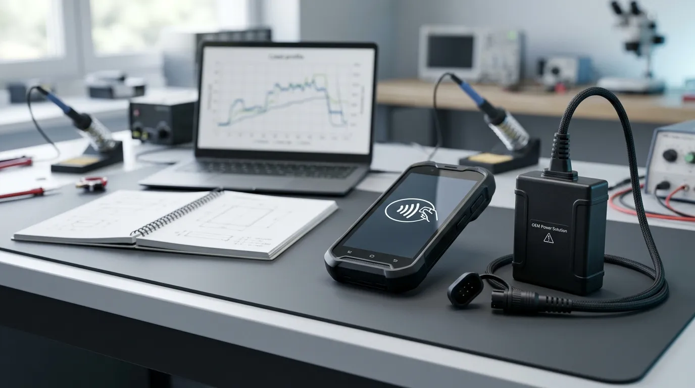
A lithium battery for mobile ticketing terminals is a rechargeable battery pack engineered specifically for handheld devices used in ticket validation and contactless payment. The correct specification cannot be determined by capacity alone—it must be derived from the terminal's measured load profile, including NFC communication bursts, display activity, wireless connectivity, and optional printing functions.
This guide explains how OEMs can translate terminal requirements into a complete battery specification, evaluate chemistry and pack architecture options, and work with a manufacturer through prototyping, validation, and production.
For a broader overview of battery selection across the full range of payment terminals, see our li ion battery for pos terminals (inferred) guide.
What Determines the Battery Requirements for a Mobile Ticketing Terminal?
A mobile ticketing terminal is not simply a "small POS device." Its battery requirements are shaped by how the terminal is actually used in the field.
Most ticketing terminals share a common set of subsystems:
- NFC/contactless reader – activates in short bursts during ticket validation and payment. The Rechargeable battery for NFC card readers is an example of how a battery can be tailored to a specific contactless workflow.
- Display and processor – draws a continuous baseline current
- Wireless communication – Wi-Fi, Bluetooth, or cellular radios create intermittent current peaks
- Barcode/QR scanner – adds short but noticeable load during ticket scanning
- Optional printer – draws the highest peak current when issuing physical receipts or tickets
Each subsystem contributes to a combined load profile—a time-based pattern of current draw that changes throughout a working shift. The load profile, not the capacity alone, determines whether a battery will deliver acceptable runtime without voltage sag or unexpected shutdowns.
How to Estimate the Load Profile and Runtime
To convert a terminal's usage pattern into a battery requirement:
- Define the duty cycle. Break the terminal's day into active, idle, and standby periods. A ticket inspector might use the terminal heavily for 30 minutes, then leave it idle for 20 minutes, repeatedly across a shift.
- Estimate average current. For each state, estimate the average current draw from the display, processor, radios, and reader. Multiply each by its time share.
- Identify peak-current windows. Printing, radio transmission, and processor-intensive tasks create short-lived current spikes that can be several times higher than the average.
- Calculate required capacity. Divide the total charge consumed over the shift by the usable capacity of the pack. This gives the required capacity in mAh or Ah at the chosen nominal voltage.
- Convert to energy. Multiply capacity (Ah) by nominal voltage (V) to obtain energy in watt-hours (Wh), which allows comparison between packs of different voltages.
- Add a design margin. Field conditions, cold temperatures, battery aging, and contact resistance all reduce usable runtime. Add margin appropriate to your deployment—there is no universal percentage.
Runtime is therefore a function of three variables: the load profile, the pack's capacity, and its ability to hold voltage under load.
Core Electrical Specifications to Define Before Contacting a Supplier
Before speaking with a battery manufacturer, define these parameters in your RFQ:
| Specification | Unit | Purpose | Notes |
|---|---|---|---|
| Nominal voltage | V | Sets the pack's standard operating voltage | Determined by series cell count |
| Maximum charge voltage | V | Upper voltage limit during charging | Must match the charger and BMS |
| Capacity | mAh or Ah | Total charge the pack can store | Does not by itself determine runtime |
| Energy | Wh | Total energy available (capacity × nominal voltage) | Useful for cross-voltage comparison and transport classification |
| Continuous current | A | Sustained current the pack can deliver | Must cover average load plus margin |
| Peak current | A | Maximum transient current and its duration | Must cover radio, printer, and processor peaks |
| Operating temperature | °C | Charge and discharge limits | State separately for charging, discharging, and storage |
| Cycle life | cycles | Expected life before capacity retention falls below a set threshold | Always specify the retention percentage and test conditions |
The series cell count determines nominal voltage. For example, a two-cell series configuration (2S) gives approximately 7.4V nominal; a three-cell series configuration (3S) gives approximately 11.1V. The parallel count determines capacity and current capability—two cells in parallel (2P) double the capacity of a single cell at the same voltage.
Choosing the Right Cell Chemistry and Pack Form Factor
The two most relevant options for a compact handheld terminal are lithium-ion (Li-ion) and lithium-polymer (Li-polymer, or LiPo).
| Chemistry | Form Factor | Typical Advantages | Trade-Offs |
|---|---|---|---|
| Li-ion | Cylindrical (e.g., 18650, 21700) | Mature production; good energy density; robust mechanical construction | Less flexible shape; may waste space in thin devices |
| Li-polymer | Pouch | Thin, flat, and custom shapes; efficient use of internal space | Requires careful mechanical protection and handling |
| LiFePO4 | Cylindrical or prismatic | Long cycle life; good thermal stability | Lower energy density; heavier for the same runtime |
For a slim, handheld terminal, Li-polymer pouch cells are often preferred because they can conform to the internal volume left after the display, battery, and other electronics are placed. Cylindrical cells remain a strong option where the design allows a straight cylindrical cavity and where mechanical robustness is a priority.
LiFePO4 is a viable alternative when cycle life and thermal stability outweigh energy density, but for most mobile ticketing terminals, the priority is maximum runtime in a compact, lightweight device, which favors Li-ion or Li-polymer.
How Series and Parallel Cell Configurations Affect Pack Performance
A battery pack is built from individual cells arranged in series and parallel.
- Series (S): Cells connected end-to-end add voltage. A 2S pack has roughly twice the nominal voltage of a single cell.
- Parallel (P): Cells connected side-by-side add capacity and current capability. A 2P pack has roughly twice the capacity of a single cell at the same voltage.
A common notation is something like "2S1P"—meaning two cells in series, one cell per parallel group. This configuration would deliver about 7.4V nominal with the capacity of a single cell. A "2S2P" pack would deliver the same voltage but twice the capacity.
Critical distinction: A cell's voltage and current ratings are not the pack's ratings. The pack's voltage is the sum of its series cells; its capacity is the sum of its parallel groups. Always verify that the datasheet refers to the pack as a whole, not to the individual cells inside it.
How BMS and PCM Protect the Battery Pack
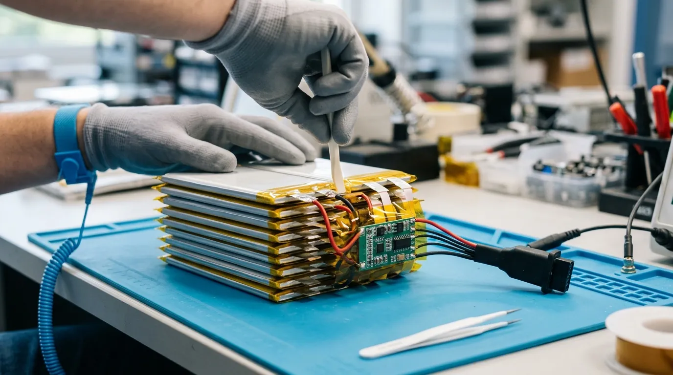
Every lithium battery pack should include protection electronics. The level of protection depends on the pack's design and the device's needs.
PCM (Protection Circuit Module) provides basic protection:
- Overcharge protection
- Over-discharge protection
- Overcurrent protection
- Short-circuit protection
- Temperature cutoff (on many designs)
BMS (Battery Management System) is a broader term that may include all PCM functions plus additional capabilities:
- Cell balancing across series groups
- State-of-charge (SOC) estimation
- State-of-health (SOH) reporting
- Data logging
- Communication interfaces such as SMBus, I2C, UART, or Bluetooth (only on specific models)
For a mobile ticketing terminal used by field staff, a BMS with fuel-gauging can be useful because the device can report remaining runtime rather than relying on a voltage-based estimate. However, a smart BMS is not a default feature—it must be specified explicitly.
The BMS protection thresholds directly limit how the pack can be charged, discharged, and used. If the terminal frequently triggers the overcurrent protection during printer operation, the BMS threshold or the pack's current capability needs to be reviewed.
Mechanical Integration, Connectors, and the Replaceable-Battery Question
The battery pack must physically fit the terminal and connect safely.
Connector and wiring:
- Pinout and polarity must be unmistakable
- Current rating must cover peak demand without overheating
- Locking or keying prevents incorrect insertion
- Wire gauge must match the continuous and peak current
Enclosure and cell mounting:
- Dimensions must match the terminal's internal cavity
- Insulation must prevent contact between cells and other components
- Mechanical protection must withstand drops and vibration typical of field use
Replaceable vs. sealed design:
A sealed pack is thinner and simpler, but when the battery degrades, the terminal must be opened—or returned—for service. A replaceable pack allows staff to swap batteries between shifts, which can reduce downtime and extend terminal life. The trade-off is a larger, more complex mechanical design.
For a fleet of ticketing terminals used across long shifts, a replaceable pack is often the better choice. Staff can carry a spare portable pos device battery and swap it in under a minute, avoiding charging downtime during the day.
Charger Compatibility and Charging Strategy
A lithium battery pack is only as reliable as its charging system.
Lithium cells charge under a CC/CV (constant current, constant voltage) profile. The charger first delivers a constant current until the pack reaches its maximum charge voltage, then holds that voltage while current tapers down.
The charger profile must match:
- The cell chemistry (Li-ion, Li-polymer, or LiFePO4 have different voltage limits)
- The series cell count (a 2S pack needs a higher charge voltage than a 1S pack)
- The recommended charge current (higher current charges faster but stresses the cells)
- The charge temperature range (charging outside this range can damage cells or create safety risk)
If the terminal charges through a USB-C port, the charging circuit must be designed to negotiate the correct voltage and current for the specific pack. A rechargeable pos terminal battery is designed to support repeated charge cycles, but the charging profile must still match the pack's chemistry and series configuration.
Environmental and Field-Use Considerations
Mobile ticketing terminals may operate outdoors, in vehicles, or in uncontrolled environments. Temperature has a direct effect on performance.
- Charging temperature is usually narrower than discharging temperature. A pack that works well on a cold ticket platform may not accept charge properly until it warms up.
- Discharge temperature affects capacity and voltage. Cold increases internal resistance, which means more voltage sag under load and less effective capacity.
- Storage temperature matters for long-term shelf life. High temperatures accelerate degradation.
Ask the battery supplier for model-specific temperature data, not a generic range. The same applies to any claimed IP rating—an IP rating describes a specific enclosure's protection against dust and water under defined test conditions. It is not the same as saying a battery is "waterproof."
Testing, Documentation, and Transport Compliance
Before a battery pack can be shipped and sold, the supplier should provide a complete documentation set.
| Document | Purpose | Key Distinction |
|---|---|---|
| Datasheet / TDS | Model-specific electrical and mechanical specifications | Applies to one model, not the whole product line |
| SDS / MSDS | Safety data for handling, storage, and transport | Identifies hazards, not certification |
| UN38.3 test summary | Documents that the battery has passed transport tests | Required for lithium-battery transport; it is not a general product-safety certificate |
| IEC/UL/CB report | Electrical product safety evidence | Applies to a defined model, construction, and standard edition |
| Manufacturer declaration (CE, RoHS, REACH) | Market-access declarations | Scope may be per product, per factory, or per component |
The most common confusion is between a UN38.3 test summary and an electrical product safety report.
According to IATA guidance, manufacturers and subsequent distributors must make the lithium-battery test summary available as specified in the UN Manual of Tests and Criteria, Revision 8, Part III, subsection 38.3, paragraph 38.3.5, subject to the stated exceptions. The U.S. Department of Transportation also provides official guidance on test-summary requirements.
A UN38.3 test summary documents that a battery has passed the transport tests required for air shipment. It does not certify that the battery is electrically safe for use in a device. That is the role of an IEC/UL product-safety report, which applies to a specific model and construction.
Similarly, an ISO 9001 certificate applies to a company's quality-management system. It is not a product certification.
When a supplier says "we are certified," ask exactly which certificate, for which model, under which standard edition, issued by which body, and valid until which date. The answer should be specific.
Common Engineering Mistakes and How to Avoid Them
Mistake 1: Treating mAh as runtime. A 5000mAh pack does not necessarily last twice as long as a 2500mAh pack if the voltage is different, the load varies, or the pack cannot sustain the required current. Always compare energy (Wh) and test under the real load profile.
Mistake 2: Under-specifying peak current. A terminal that prints receipts or transmits large data bursts may draw several times its average current for short periods. If the pack cannot deliver peak current, voltage sag causes resets or shutdowns.
Mistake 3: Ignoring voltage sag and internal resistance. Internal resistance causes the pack voltage to drop under load. High internal resistance—from cold, aging, or poor cell matching—causes the terminal to shut down while still showing a high state of charge at rest.
Mistake 4: Mismatching the charger and the pack. A charger designed for a 3S pack will overcharge a 2S pack. A charger with the wrong charge voltage or current profile will degrade cells and may create a safety hazard.
Mistake 5: Copying another device's battery specification. A spec that works for a handheld scanner may not work for a ticketing terminal with a printer and cellular radio. The specification must be derived from your device's actual load profile.
Mistake 6: Accepting a certificate without checking scope. A supplier may hold a certificate for one model but claim it for the entire product range. Always verify the model number, standard edition, issuing body, and validity date.
How to Write an RFQ and Evaluate a Battery Supplier
A well-structured RFQ prevents ambiguity and reduces the chance of receiving a pack that does not meet your requirements.
Include in your RFQ:
- Device description and load profile (average current, peak current, duty cycle)
- Nominal voltage and maximum charge voltage
- Required capacity (mAh or Ah) and energy (Wh)
- Continuous and peak current requirements
- Dimensions and weight limits
- Connector type, pinout, and wiring requirements
- Charging method (USB-C, dedicated charger, etc.)
- Temperature range (charging, discharging, storage)
- Target cycle life and retention threshold
- Required documentation (datasheet, UN38.3, IEC/UL, SDS/MSDS)
- Prototype and pilot production requirements
- Quality agreement, change control, and traceability requirements
Supplier evaluation questions:
- Which cell manufacturer do you use, and can you share the cell datasheet?
- How do you match cells within a pack?
- What are the exact BMS protection thresholds for this pack?
- Can you provide the UN38.3 test summary for this specific model?
- Does the IEC/UL report cover this model and construction, or a different model?
- What is your change-control process if a cell, BMS, or connector changes?
- What is the MOQ for a custom design, and what is the lead time for prototypes?
- What is your warranty and after-sales support policy?
A supplier that cannot answer these questions specifically is unlikely to deliver a reliable OEM pack.
How Gloflux Supports OEM Battery Development for Portable Terminals
Gloflux is a lithium-battery manufacturer offering custom battery development for OEM applications, including POS and payment terminals. We support the full process from requirements capture through prototype, validation, and mass production.
Our engineers work directly with your load profile, mechanical constraints, and documentation requirements to define the right chemistry, pack architecture, BMS, and connector configuration for your device.
Example: One of our verified battery configurations is a 7.4V 2600mAh Li-ion battery designed for mobile POS terminals and handheld printers. It demonstrates how a specific voltage and capacity are matched to a real device requirement. Your terminal will likely have a different specification—which is exactly the point. The specification must be derived from your device, not copied from another product.
Gloflux's application page for POS and payment terminals provides further context on how we approach handheld payment device power. For a broader look at how we support custom pack development, visit our custom battery solutions page.
If you have a mobile ticketing terminal in development, send us your load profile and mechanical constraints, and we will work with you to define the correct battery specification.
Frequently Asked Questions
What type of battery does a mobile ticketing terminal use?
A mobile ticketing terminal typically uses a rechargeable lithium-ion or lithium-polymer battery pack. The exact chemistry, voltage, capacity, and form factor must be derived from the terminal's load profile, mechanical design, and field-use conditions.
What is the difference between a UN38.3 test summary and a product safety report?
A UN38.3 test summary documents that a battery has passed the transport safety tests required for lithium-battery shipment. An IEC/UL product-safety report certifies that a specific battery model meets defined electrical-safety standards. They serve different purposes and are both required for a fully documented OEM battery.
Should the battery be replaceable in a mobile ticketing terminal?
It depends on the deployment model. A replaceable pack allows field staff to swap batteries between shifts, reducing downtime. A sealed pack allows a thinner, simpler device design but requires the terminal to be opened or returned for service when the battery degrades.
How do I calculate battery runtime for my terminal?
Runtime depends on the load profile, not capacity alone. Estimate average current across the duty cycle, divide the pack's usable capacity by that average current, then add margin for cold temperatures, aging, and voltage sag under peak loads.
Can I use the same battery for a POS terminal and a ticketing terminal?
Potentially, if the electrical, mechanical, and environmental requirements match. But a battery specified for one device may not cover the other's load profile. Always verify voltage, capacity, current, connector, and dimensions against the actual terminal design.
Talk to the Manufacturer
Resources & Insights

High Capacity Lithium Battery for Wearables: High-Voltage LiPo Cell Design
2026-10-19

Cylindrical Battery Packs for Laptops: 2S vs 3S vs 4S Battery Design
2026-10-19

Stage Lighting Battery Pack: Prevent Voltage Drop & LED Flicker
2026-10-19

Best Rechargeable Batteries for Smart Devices: Performance, Safety, and Selection Guide
2026-10-19


