


 Home /
 Rechargeable Battery for NFC Card Readers: Compact OEM Design


Table of Contents
- What Powers a Battery-Operated NFC Reader?
- Li-ion vs. LiPo: Which Is Better for a Compact NFC Reader?
- Cell vs. Battery Pack: What Do You Actually Need?
- How to Specify the Electrical Parameters
- Protection, BMS, and Charging
- Mechanical Integration: Connector, Enclosure, and Thermal Path
- Testing, Validation, and Documentation
- How to Choose and Evaluate a Battery Supplier
- FAQ
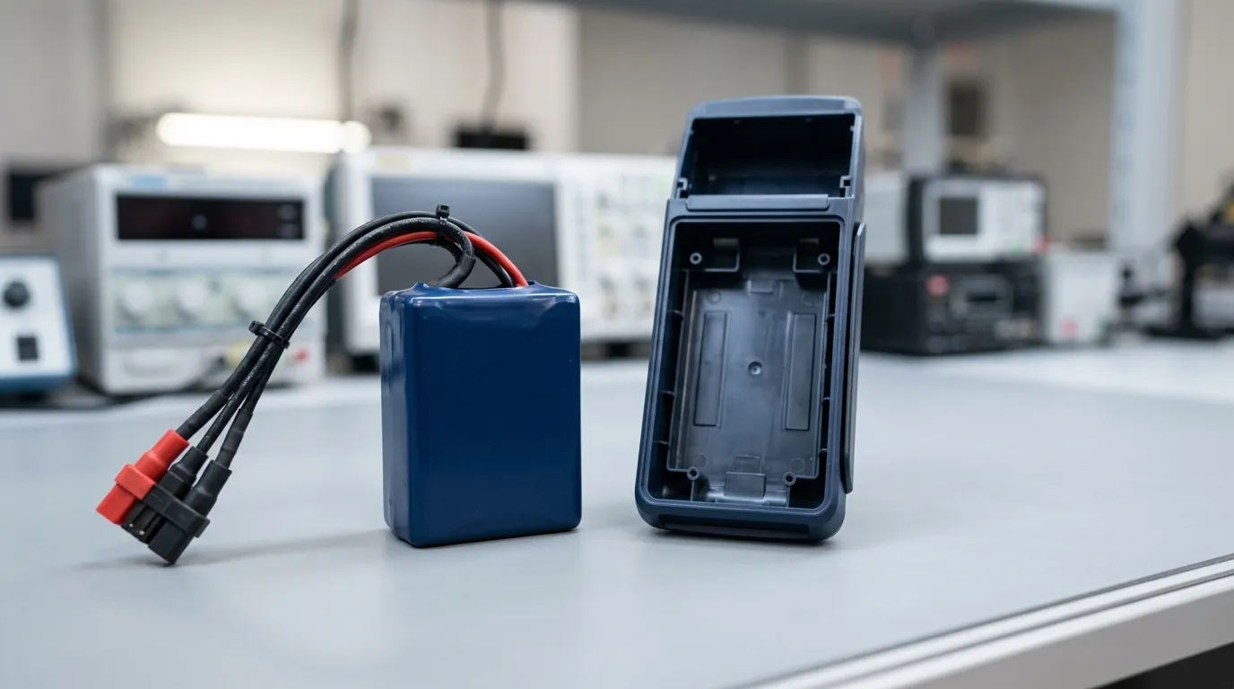
A rechargeable battery for an NFC card reader is a compact, protected battery pack—typically lithium-ion or lithium-polymer—selected to match the reader's voltage requirements, load profile, charging interface, mechanical envelope, and documentation needs. The correct specification is device-specific and depends on what the reader actually powers during operation.
This guide is for OEMs and engineers developing portable, battery-powered NFC readers—not passive NFC tags, which draw power from the reading device, and not host-powered readers that operate from a USB or fixed supply. For broader guidance on POS terminal battery design and customization, see our li ion battery for pos terminals (inferred) guide.
What Powers a Battery-Operated NFC Reader?
The battery in a portable NFC reader does not just power the NFC antenna. It must supply the complete device load, which typically includes:
- Wireless radios (Bluetooth and/or NFC) for communication with a host device or payment terminal.
- Processor and memory for transaction processing and security functions.
- Display (if present) for status messages, PIN entry, or transaction feedback.
- Card detection circuitry that wakes the reader when a card is presented.
- Status LEDs and buzzers for user feedback.
- Optional peripherals such as a small printer or biometric sensor.
The load profile—how much current the device draws and for how long—determines the battery requirement. A reader that spends most of its time in low-power standby and only wakes for short card-reading bursts has a very different battery requirement than one with a constantly active display and continuous Bluetooth streaming.
The key specification is not the NFC interface itself but the average and peak current demand of the complete reader during its operating cycle.
Li-ion vs. LiPo: Which Is Better for a Compact NFC Reader?

The two most common rechargeable options for compact NFC readers are lithium-ion (Li-ion) and lithium-polymer (LiPo) pouch cells. Both use lithium-ion chemistry, but they differ in construction and packaging.
| Criterion | Li-ion (Cylindrical or Prismatic) | Li-Polymer (Pouch) |
|---|---|---|
| Form factor | Fixed cylindrical or prismatic dimensions | Thin, flexible, shape-customizable |
| Thickness | Usually thicker (typically >5 mm for 18650/21700) | Can be very thin (2–5 mm typical for reader designs) |
| Energy density | Generally high | Can be comparable, depending on the cell |
| Custom shapes | Limited | Can be manufactured in custom shapes to fit unusual enclosures |
| Packaging | Rigid metal can or hard prismatic case | Soft aluminum-polymer pouch, requires mechanical protection in the pack |
| Cycle life | Can be long at moderate discharge rates | Can be long at moderate discharge rates |
| Charging | Standard Li-ion CC/CV profile | Same Li-ion charging profile |
| Safety | Rigid enclosure provides some protection | Pouch can swell if overcharged or damaged; requires BMS protection and enclosure design |
Which is better for a compact NFC reader?
- LiPo pouch cells are often the better fit when the reader is thin, has an irregular enclosure, or has strict weight limits. The ability to shape the cell to the available space is a significant advantage in compact device design.
- Li-ion cylindrical cells (such as 18650 or 21700) are a practical choice when the enclosure can accommodate a cylindrical form factor, and when higher available capacity or standardized cell supply is important.
- The decision depends on your enclosure dimensions, weight target, custom-shape requirements, current demand, and thermal design.
There is no universal winner. The correct choice is the one that fits your reader's mechanical and electrical constraints. For a broader comparison of battery types for portable payment hardware, see our guide on portable pos device battery.
Cell vs. Battery Pack: What Do You Actually Need?
A common specification error is confusing a bare cell with a complete battery pack.
| Component | What It Is | What It Includes |
|---|---|---|
| Bare cell | A single electrochemical unit | Electrodes, electrolyte, separator, and a basic can or pouch. No protection, no connector, no enclosure. |
| Battery pack | An assembled unit designed for a device | One or more cells, plus a PCM/BMS, connector(s), wiring, enclosure/insulation, and possibly a fuel gauge or temperature sensor. |
For a portable NFC reader, you almost always need an integrated battery pack, not a bare cell. A bare cell offers no protection against overcharge, over-discharge, or short circuit, and it does not provide a user-friendly connector or mechanical mounting.
If you are sourcing from an OEM like Gloflux, you are typically designing and ordering a complete pack that includes the cell configuration, protection electronics, connector, and enclosure—not just a cell.
How to Specify the Electrical Parameters
To specify the correct pack, you need to define the following parameters for your NFC reader:
1. Nominal Voltage
The nominal voltage is the pack's rated operating voltage, determined by the cell chemistry and the series (S) configuration.
- A single-cell (1S) Li-ion or LiPo pack has a nominal voltage of 3.7 V and a maximum charge voltage of 4.2 V.
- A two-series (2S) pack has a nominal voltage of 7.4 V and a maximum charge voltage of 8.4 V.
Your reader's input voltage range determines whether you need a 1S, 2S, or higher series count.
2. Maximum Charge Voltage
Do not confuse nominal voltage with maximum charge voltage. The charger must be designed for the pack's charge voltage:
- Li-ion/LiPo: typically 4.2 V per series cell (some chemistries use 4.35 V per cell).
- LiFePO4: typically 3.65 V per series cell—but this chemistry is less common in compact readers because its lower nominal voltage (3.2 V per cell) requires a different system design.
3. Capacity (mAh/Ah) vs. Energy (Wh)
- Capacity is measured in mAh or Ah and indicates the total charge the pack can store.
- Energy is measured in Wh and is the more useful value for runtime comparison because it accounts for voltage.
For example:
- A 3.7 V pack with 2000 mAh provides 7.4 Wh of energy.
- A 7.4 V pack with 1000 mAh also provides 7.4 Wh, but at a different voltage.
When comparing packs with different voltages, always use Wh.
4. Continuous and Peak Current
You must define both:
- Continuous current (A): the steady current the pack must supply during normal operation (e.g., during a card-reading transaction or Bluetooth communication).
- Peak current (A): the short-duration current the pack must supply during high-load events (e.g., display refresh, radio transmit, or motor/solenoid actuation).
The pack's C-rate is the current expressed as a multiple of capacity. A 2000 mAh (2 Ah) pack rated at 1C can deliver 2 A continuously. The C-rate tells you how the pack performs relative to its capacity, but the actual current in amperes is what your reader consumes.
5. Runtime Calculation
You can estimate runtime using this method:
Runtime (h) ≈ Pack Energy (Wh) ÷ Average System Load (W)
For example:
- Pack energy: 7.4 Wh
- Average system load: 0.5 W (averaging standby, active reading, and wireless transmission)
- Estimated runtime: 7.4 Wh ÷ 0.5 W ≈ 14.8 hours
This is a calculated estimate, not a certified specification. It assumes a stable average load and does not account for voltage sag, temperature effects, self-discharge, or battery aging. Always verify runtime with a prototype under real operating conditions.
6. Internal Resistance and Voltage Sag
Internal resistance (measured in milliohms) causes voltage sag under load. A pack with high internal resistance may drop below the reader's minimum operating voltage during a current spike, causing a reset or unexpected shutdown—even though the pack still has charge remaining.
For an NFC reader with frequent short high-current events (radio transmits, display refreshes), choose a pack with low internal resistance and verify sag behavior during prototype testing.
Protection, BMS, and Charging
PCM vs. BMS: What's the Difference?
| Feature | PCM (Protection Circuit Module) | BMS (Battery Management System) |
|---|---|---|
| Overcharge protection | Yes | Yes |
| Over-discharge protection | Yes | Yes |
| Overcurrent protection | Yes | Yes |
| Short-circuit protection | Yes | Yes |
| Temperature protection | Often | Yes |
| Cell balancing (multi-series) | Not typically | Yes |
| Fuel gauge / state of charge | Not typically | Yes (smart BMS) |
| Communication (SMBus, I2C, UART, CAN) | Not typically | Yes (smart BMS) |
| Data logging | No | Yes (smart BMS) |
- A PCM provides basic protection and is sufficient for many single-cell (1S) designs.
- A smart BMS adds balancing (for multi-series packs), state-of-charge estimation via a fuel gauge, and communication protocols if your reader needs to report battery health or remaining runtime.
For a compact NFC reader with a single cell, a basic PCM may be enough. For a 2S or higher pack, or if you need battery telemetry, choose a smart BMS.
Charging Requirements
The charger must match the pack's chemistry, series count, and charge limits:
- Li-ion/LiPo uses a CC/CV (constant current / constant voltage) charging profile.
- The charger IC must be configured for the pack's maximum charge voltage and charge current.
- USB and USB-C are common charging interfaces for portable readers, but the charger IC, not the connector alone, determines compatibility.
Critical points:
- Charge current must not exceed the pack's specified maximum charge rate (often 0.5C to 1C for Li-ion/LiPo, depending on the cell).
- Charge temperature range is narrower than the discharge range (typically 0°C to 45°C for Li-ion). Attempting to charge below 0°C can cause lithium plating and permanent damage.
- Charge termination (when the charger stops) must be set correctly to avoid overcharging.
Mechanical Integration: Connector, Enclosure, and Thermal Path
The electrical specification is only half the design. The pack must physically fit and connect correctly.
Connector and Wiring
- Connector pinout and polarity must be documented precisely. A reversed connection can destroy the reader's electronics.
- Wire gauge must be sized for the peak current. A wire that is too thin will heat up and cause voltage drop.
- Connector locking is advisable in portable devices to prevent disconnection during drops or vibration.
Enclosure
- The pack needs mechanical protection from impact, vibration, and crushing.
- Dimensions must fit the reader's internal cavity with clearance for the connector and wiring.
- Weight affects the reader's portability and ergonomics.
- Do not rely on a soft pouch cell alone for mechanical protection; the enclosure must support and retain the pack.
Thermal Path
Batteries generate heat during charging and high-current discharge. In a compact, sealed enclosure, that heat has nowhere to go unless you design a thermal path:
- Provide a thermal interface between the pack and the enclosure or a heat spreader.
- Ensure the charging temperature stays within the pack's specified range.
- Test for temperature rise during continuous operation and fast charging.
IP Rating
An IP rating (e.g., IP54) applies only if your reader specifies an ingress-protection requirement. An IP rating is a tested, standardized classification—not the same as generic "water-resistant" or "waterproof" language. If you need an IP rating, the entire device (including the battery enclosure and connector) must be designed and tested to that standard.
Testing, Validation, and Documentation
Before moving to production, validate the battery pack with a prototype and request the correct documentation from your supplier.
Prototype Validation Checklist
| Test | What to Confirm |
|---|---|
| Dimensions and fit | The pack fits the enclosure with clearance for connector and wiring. |
| Connector fit and polarity | The connector mates correctly with no reverse-polarity risk. |
| Open-circuit voltage | Matches the specified nominal voltage. |
| Capacity test | Measured capacity meets the datasheet value under specified conditions. |
| Continuous current test | The pack sustains the reader's continuous load without excessive voltage sag or temperature rise. |
| Peak current test | The pack handles specified transient loads without dropping below the reader's cutoff voltage. |
| Charge test | The charger terminates correctly at the specified charge voltage and current. |
| Temperature rise | The pack and enclosure stay within specified limits during charge and discharge. |
Documentation to Request from Your Supplier
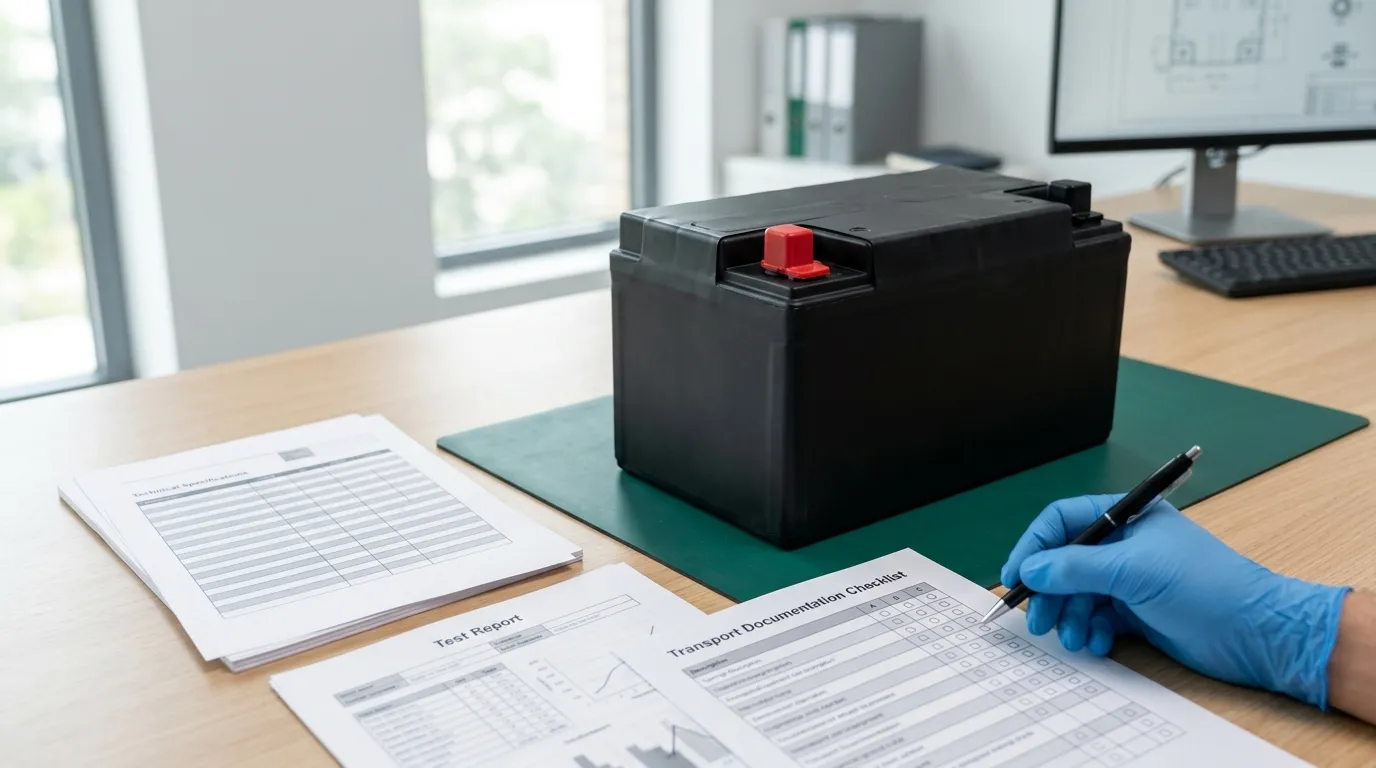
| Document | What It Provides |
|---|---|
| Datasheet / TDS | Exact electrical and mechanical specifications, test conditions, and limits for the specific model. |
| UN38.3 test summary | Evidence that the battery has passed the UN transport tests required for lithium-battery shipment by air, sea, and ground. |
| IEC 62133 / UL report | Product-safety testing evidence for a defined model and standard scope. Not automatically present; depends on market and device requirements. |
| SDS / MSDS | Safety data for handling, storage, and transport. |
| Capacity and aging test reports | Batched production data confirming capacity and stability. |
| Traceability records | Lot/batch tracking for quality control and change management. |
Important distinction: A UN38.3 test summary is a transport requirement—it confirms the battery can be shipped legally. An IEC 62133 or UL report is a product-safety benchmark that applies to a defined model and construction. They are not interchangeable. You may need both, depending on your market and transport routes.
For more on lithium-battery transport requirements, the U.S. Department of Transportation (PHMSA) requires that manufacturers provide a test summary for lithium cells and batteries, as described in the UN test summary requirement. The specific test criteria are detailed in the UN Manual of Tests and Criteria. Transport guidance for air shipment is published by IATA.
For a general explanation of battery testing against international standards, see this overview of UN38.3, IEC 62133, and related testing from TÜV SÜD.
How to Choose and Evaluate a Battery Supplier
Selecting a battery supplier is a technical and commercial decision. Use this checklist to guide your evaluation:
Define Your Requirements First
Provide the supplier with:
- Nominal and charge voltage required by the reader.
- Capacity target (mAh/Ah) and energy target (Wh) for the desired runtime.
- Continuous and peak current with durations.
- Mechanical envelope: dimensions, weight, connector type, and orientation.
- Charging interface: USB/USB-C, charger IC, charge current.
- BMS/PCM requirements: protection features, balancing, fuel gauge, communication protocol.
- Environmental conditions: operating and storage temperature range.
- Documentation required: datasheet, UN38.3 test summary, SDS, test reports, traceability records.
RFQ Checklist
Ask the supplier:
- Do you have a validated pack that meets these specifications, or can you customize one?
- What is the MOQ and lead time for prototype samples and production?
- Are NRE/tooling costs required for custom enclosure or connector tooling?
- Can you provide a datasheet/TDS with exact test conditions for the proposed pack?
- Do you provide a UN38.3 test summary for the specific model, and can you ship the battery in full compliance?
- What testing and quality-control records do you keep (capacity tests, aging, traceability by lot/batch)?
- What is your change-control policy? Will you notify me before any cell, BMS, connector, or process change?
- What warranty and after-sales support do you provide?
Why Gloflux for Compact OEM Battery Packs?
Gloflux is a lithium-battery manufacturer focused on custom OEM/ODM battery development, covering cell selection, pack architecture, BMS/protection, connector and wiring, enclosure design, prototyping, testing, certification support, and mass production.
For POS and payment-terminal applications, Gloflux offers POS and payment-terminal battery solutions that include lithium-polymer, high-capacity lithium-ion, cylindrical, and custom-shaped packs—with protection features such as overcharge, over-discharge, short-circuit, overcurrent, and temperature protection.
If you are developing a compact NFC reader and need a battery pack that fits your enclosure and load profile, the most efficient next step is to submit your battery requirement for a feasibility review. Provide your voltage, current, runtime, mechanical envelope, and documentation needs—Gloflux's engineering team can confirm whether an existing solution fits or a custom pack design is required.
For broader guidance on rechargeable battery design for POS and payment terminals, see our rechargeable pos terminal battery guide. If your reader pairs with mobile receipt printers, also review our Custom battery for portable label printers page.
FAQ
What voltage does an NFC reader battery need?
Most compact NFC readers use a 1S Li-ion or LiPo pack with a nominal voltage of 3.7 V and a maximum charge voltage of 4.2 V. The exact voltage depends on your reader's input range. Some designs with higher power requirements use a 2S pack at 7.4 V nominal (8.4 V maximum). Always verify the reader's input voltage specification before selecting the pack.
How do I calculate runtime from battery capacity?
Use energy (Wh), not just capacity (mAh), for runtime estimation:
Runtime (h) ≈ Pack Energy (Wh) ÷ Average System Load (W)
A 3.7 V, 2000 mAh pack provides 7.4 Wh. If your reader's average load is 0.5 W, the estimated runtime is about 14.8 hours. This is a calculated estimate that must be validated with a prototype under real conditions.
Do NFC readers need a battery?
Only battery-powered, portable NFC readers need a battery. Many NFC readers are host-powered, operating from a USB or fixed power supply. Passive NFC tags have no battery at all—they draw power from the reading device. This article addresses portable, battery-powered readers.
What is the difference between UN38.3 and IEC 62133?
UN38.3 is a transport requirement—it confirms that a lithium battery can be shipped safely by air, sea, and ground. A UN38.3 test summary must be provided by the manufacturer for the specific battery model. IEC 62133 is a product-safety standard that applies to a defined battery model and construction, depending on your target market. You may need both, but they are not interchangeable.
Talk to the Manufacturer
Resources & Insights

High Capacity Lithium Battery for Wearables: High-Voltage LiPo Cell Design
2026-10-19

Cylindrical Battery Packs for Laptops: 2S vs 3S vs 4S Battery Design
2026-10-19

Stage Lighting Battery Pack: Prevent Voltage Drop & LED Flicker
2026-10-19

Best Rechargeable Batteries for Smart Devices: Performance, Safety, and Selection Guide
2026-10-19


