


 Home /
 Rechargeable Battery for Handheld Diagnostic Devices: OEM Selection Guide


Table of Contents
- Step 1 — Define the Device Load Profile
- Step 2 — Calculate Voltage, Capacity, and Energy
- Step 3 — Choose the Right Chemistry and Form Factor
- Step 4 — Decide Series and Parallel Configuration
- Step 5 — Plan Protection, BMS, and Charging Strategy
- Step 6 — Evaluate Mechanical and Thermal Integration
- Step 7 — Confirm Safety, Transport, and Documentation
- Step 8 — Qualify Your Supplier and Build the RFQ
- Industry Context — Handheld Diagnostic Devices
- FAQ
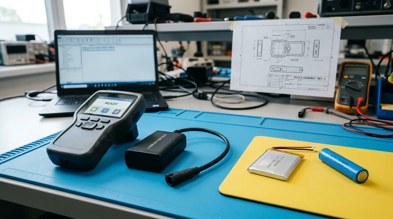
A rechargeable battery for handheld diagnostic devices must be specified from the device's actual operating requirements — voltage, average and peak current, runtime, physical envelope, charging method, temperature range, and safety documentation — not from capacity alone. For OEMs, selecting the right battery pack means translating clinical and mechanical requirements into an electrical specification that a qualified supplier can engineer, test, and document.
This guide walks through the eight decisions that define a handheld diagnostic device battery, from load profiling through supplier qualification. For a broader view of battery options across medical equipment, see our medical device battery pack solutions.
Step 1 — Define the Device Load Profile
Every handheld diagnostic device presents a unique electrical load. A pulse oximeter, a portable ultrasound probe, and a handheld blood analyzer draw power differently, and those differences determine the battery specification.
Start by measuring or estimating the current draw for each operating mode:
- Continuous baseline: display, processor, sensor polling.
- Periodic functions: wireless transmission, data logging, motor or pump operation.
- Peak events: alarm activation, high-intensity illumination, defibrillation or therapeutic pulses, motor startup.
Separate continuous current — the sustained draw during normal operation — from peak current, which may last only milliseconds or seconds but can be several times higher than the baseline. A battery pack that handles the average load but cannot deliver the peak current will experience voltage sag, brownouts, or unexpected resets.
Also define the duty cycle: how long the device operates continuously, how often it returns to standby or charge, and how long it must run between charges. The runtime target, combined with the load profile, sets the minimum usable energy requirement.
| Operating Mode | Typical Current Draw | Duration | Impact on Battery Spec |
|---|---|---|---|
| Sleep / standby | Low (µA–mA) | Hours | Self-discharge, shelf life |
| Continuous measurement | Moderate (mA) | Minutes–hours | Capacity, continuous current |
| Wireless transmission | High (A) | Seconds–minutes | Peak current, thermal |
| Alarm / pulse | Peak (A) | Milliseconds–seconds | Peak current, C-rate |
Step 2 — Calculate Voltage, Capacity, and Energy
Once the load profile is defined, the electrical specification divides into three values that are often confused.
Nominal voltage is the rated midpoint of the battery's discharge curve. For a lithium-ion cell, this is approximately 3.6–3.7 V. The pack's nominal voltage depends on how many cells are connected in series.
Capacity, measured in milliamp-hours (mAh) or amp-hours (Ah), indicates how much charge the battery can store. It does not tell you the total energy. A 2000 mAh battery at 3.7 V stores less energy than a 2000 mAh battery at 7.4 V.
Energy, measured in watt-hours (Wh), combines voltage and capacity:
Wh = Nominal voltage (V) × Capacity (Ah)
For a handheld diagnostic device requiring 5 W average power for 8 hours, the usable energy requirement is:
5 W × 8 h = 40 Wh
At 7.4 V nominal, this corresponds to approximately 5.4 Ah (5400 mAh) of rated capacity, before accounting for system efficiency, voltage cutoff, self-discharge, and aging.
Also note the difference between nominal voltage and maximum charge voltage. A lithium-ion cell charges to approximately 4.2 V, so a 2S pack (two cells in series) has a nominal voltage of 7.4 V but a charge voltage of 8.4 V. The charger, protection circuit, and device input must all be rated for the charge voltage.
Step 3 — Choose the Right Chemistry and Form Factor
Most handheld diagnostic devices use one of three rechargeable chemistries, each with different trade-offs.
Lithium-Ion (Li-ion, Cylindrical)
Li-ion cylindrical cells — most commonly 18650 and 21700 formats — offer high energy density, mature manufacturing, and broad availability. They are suited to devices with moderate space and a defined cylindrical cavity.
- Advantages: High energy density, low self-discharge, long cycle life in quality cells, established supply chain.
- Limitations: Rigid cylindrical shape; requires space for cell holders and insulation; thermal management needed under high discharge.
Lithium-Polymer (LiPo, Pouch)
LiPo pouch cells use a flexible aluminum-laminated casing, allowing thin or irregular shapes that fit ergonomic handheld designs.
- Advantages: Thin profile, shape flexibility, lightweight.
- Limitations: Requires mechanical protection against puncture; swelling risk under abuse or aging; slightly lower energy density than the best cylindrical cells.
Lithium Iron Phosphate (LiFePO4)
LiFePO4 offers a nominal voltage of 3.2 V per cell and a very flat discharge curve.
- Advantages: Excellent thermal and chemical stability, long cycle life, tolerant of higher temperatures.
- Limitations: Lower energy density than Li-ion/LiPo; higher weight and volume for the same energy; requires a charger and BMS matched to its voltage profile.
Nickel-Metal Hydride (Ni-MH)
Ni-MH is an older chemistry still found in some legacy or low-cost portable devices.
- Advantages: Lower cost; no lithium transport restrictions; simple charging in some configurations.
- Limitations: Lower energy density, higher self-discharge, memory effect if improperly charged, shorter cycle life.
For most new handheld diagnostic devices, Li-ion or LiPo is the practical default. LiFePO4 becomes attractive when thermal stability or cycle life outweighs energy density. Ni-MH remains a legacy or cost-constrained option. For a broader discussion of chemistry selection in medical applications, see our guide to lithium ion battery for medical devices.
| Chemistry | Nominal Cell Voltage | Energy Density | Cycle Life | Best Use Case |
|---|---|---|---|---|
| Li-ion (cylindrical) | 3.6–3.7 V | High | Good | Standard form factors, high capacity |
| LiPo (pouch) | 3.7 V | Medium-high | Moderate–good | Thin, custom-shaped devices |
| LiFePO4 | 3.2 V | Medium | Excellent | High-temperature or long-life applications |
| Ni-MH | 1.2 V | Low-medium | Moderate | Legacy or very low-cost devices |
Step 4 — Decide Series and Parallel Configuration
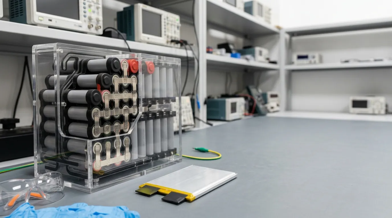
The pack's electrical architecture is defined by its series (S) and parallel (P) configuration.
Series cells (S) add voltage. A pack with two 3.7 V cells in series (2S) has a nominal voltage of 7.4 V and a charge voltage of 8.4 V.
Parallel cells (P) add capacity and current capability at the same voltage. A 2P pack has two cells in parallel, doubling the capacity and current-handling ability compared to a single cell.
For example, a 2S2P pack uses four cells: two in series to reach 7.4 V nominal, and two parallel groups to double capacity. The exact configuration depends on the cell's rated capacity and the device's current demand.
| Configuration | Nominal Voltage | Relative Capacity | Typical Use |
|---|---|---|---|
| 1S1P | 3.7 V | 1× cell capacity | Small sensors, single-cell devices |
| 1S2P | 3.7 V | 2× cell capacity | Low-voltage devices, higher current |
| 2S1P | 7.4 V | 1× cell capacity | Higher-voltage devices |
| 2S2P | 7.4 V | 2× cell capacity | Longer runtime at higher voltage |
Matching the configuration to the load profile prevents two common design errors: under-specifying peak current (too few parallel cells) and over-specifying voltage (more series cells than the device needs). Gloflux supports custom S/P architectures to match the device requirement — for more detail, see our custom battery packs.
Step 5 — Plan Protection, BMS, and Charging Strategy
A battery pack is more than cells. The protection and management electronics determine safety, reliability, and how the pack communicates with the device.
PCM (Protection Circuit Module)
A PCM provides basic protection against:
- Overcharge
- Over-discharge
- Overcurrent
- Short circuit
It is a simple, low-cost protection layer. It does not typically provide cell balancing, state-of-charge reporting, or communication.
BMS (Battery Management System)
A BMS includes protection functions and adds management features, most commonly cell balancing for multi-series packs. Balancing keeps series cells at similar voltages, which supports pack consistency and usable cycle life.
A smart BMS adds monitoring and communication — fuel gauging, state of charge (SoC), state of health (SoH), data logging, and interfaces such as SMBus, I2C, UART, or CAN. A fuel gauge estimates remaining runtime from current, voltage, and temperature, which is valuable for a diagnostic device that must warn the clinician before shutdown.
Charger Compatibility
The charger must match the pack's chemistry, series count, and voltage limits. Most lithium packs use the CC/CV (constant current / constant voltage) method: the charger applies a constant current until the pack reaches its charge voltage, then holds that voltage while current tapers. A charger designed for a 2S pack cannot charge a 3S pack safely. The connector, polarity, and charge-current rating must also match the pack specification.
| Feature | PCM | Basic BMS | Smart BMS |
|---|---|---|---|
| Overcharge / over-discharge / overcurrent / short-circuit protection | Yes | Yes | Yes |
| Cell balancing | No | Yes | Yes |
| State-of-charge / fuel gauge | No | No | Yes |
| Communication (SMBus, I2C, CAN, etc.) | No | No | Yes |
| Data logging | No | No | Optional |
Step 6 — Evaluate Mechanical and Thermal Integration
The battery pack must fit the device envelope, survive its operating environment, and manage heat.
Enclosure: The pack may be a rigid plastic shell, a heat-sealed pouch, or an integrated compartment within the device housing. The enclosure must protect cells from impact, vibration, and ingress of fluids or dust. If the device is cleaned with wipes or sprays, consider the pack's ingress protection (IP) rating. An IP rating describes protection against solid objects and water — "water-resistant" or "waterproof" without a rating does not define the condition.
Connector: The connector must match the device's charging and power interface. Specify orientation, locking mechanism, current rating, and whether the battery is user-replaceable. A connector that cannot handle peak current creates a resistive contact and voltage drop.
Thermal management: Lithium cells generate heat under load and during charging. High discharge rates and ambient temperature affect voltage sag, cycle life, and safety. Define the device's operating and storage temperature ranges, and consider how the enclosure conducts heat away from the cells. In a handheld device, the battery pack and the clinician's hand share the same thermal envelope — the surface temperature must remain comfortable and within safety limits.
Also define the charge temperature and discharge temperature separately. A pack that operates at 0°C discharge may not be safely chargeable at that temperature.
Step 7 — Confirm Safety, Transport, and Documentation
A rechargeable battery for a handheld diagnostic device carries distinct documentation obligations. Three categories are commonly confused.
UN 38.3 — Transport Testing
Lithium cells and batteries must pass the UN Manual of Tests and Criteria, Section 38.3, before air transport. The tests cover altitude simulation, thermal cycling, vibration, shock, external short circuit, impact, overcharge, and forced discharge. A UN 38.3 test summary documents that a specific cell or battery type met these requirements. It is a transport document — it does not certify the battery as a medical device or prove product safety for all applications.
IEC 62133-2 — Battery Safety Standard
IEC 62133-2 specifies requirements and tests for the safe operation of portable sealed secondary lithium cells and batteries — covering abuse conditions and intended use. This standard is relevant to battery pack design and supplier qualification. FDA recognizes IEC 62133-2 as a consensus standard for medical device batteries. Note that compliance applies to a defined cell or pack construction, not to the entire product line of a manufacturer.
IEC 60601-1 — Medical Electrical Equipment
IEC 60601-1 applies to the complete medical electrical device, not the battery alone. The battery is one subsystem within the device's overall safety and EMC compliance. A battery that meets IEC 62133-2 has not automatically met IEC 60601-1 — the device OEM carries the responsibility for system-level compliance.
Documentation to Request From a Supplier
- Datasheet / TDS: electrical, mechanical, and environmental ratings with test conditions.
- UN 38.3 test summary: transport qualification for the specific pack.
- Test reports: IEC 62133-2 or other applicable safety standards.
- SDS/MSDS: safety data for handling, storage, and transport.
- Certificate of origin or compliance: CE, RoHS, REACH, or other market-specific declarations, where applicable.
The distinction between documents matters. A manufacturer's ISO 9001 certificate describes its quality management system — it does not certify a specific battery model.
Step 8 — Qualify Your Supplier and Build the RFQ
The best battery specification fails if the supplier cannot engineer, test, and document it correctly. The skill lies in writing an RFQ that receives comparable and verifiable responses.
What to Include in the RFQ
| Category | Required Information |
|---|---|
| Electrical | Nominal voltage, charge voltage, capacity (mAh/Ah), continuous current (A or C-rate), peak current and duration, charger profile |
| Mechanical | Max dimensions (mm), weight limit, connector type, wiring length, mounting method |
| Environmental | Operating temperature (charge and discharge separately), storage temperature, IP rating if required |
| Runtime | Target runtime under stated load, acceptable voltage cutoff |
| Battery management | PCM only, basic BMS, or smart BMS; fuel gauge; communication protocol |
| Documentation | Datasheet, UN 38.3 summary, test reports, SDS/MSDS, traceability records |
| Validation | Prototype requirements, testing plan, sample approval process, pilot-run criteria |
| Supply terms | MOQ, lead time, change control process, warranty terms |
How to Evaluate Supplier Responses
Compare the datasheet numbers — not just the headline voltage and capacity. Check:
- Whether the continuous current rating meets your peak load with margin.
- Whether the C-rate is realistic for your load profile. A 2000 mAh pack rated at 1C delivers 2 A continuous; at 3C it delivers 6 A. C-rate and amperage are different ways of describing the same current, and both must appear in the datasheet.
- Whether the cycle life figure includes the retention threshold and test conditions. "500 cycles" without a stated end-of-life capacity is incomplete.
- Whether temperature limits apply to charging, discharging, or storage. They are three different specifications.
- Whether the connector and charging interface match your device design.
- Whether the supplier has a change control process — requiring notification before substituting cells, BMS components, or manufacturing processes after your approval. This protects the approved design from hidden variation.
Prototype and Pilot
Never jump from datasheet to mass production. Request a prototype for:
- Electrical validation under your actual load profile.
- Mechanical fit within the device envelope.
- Thermal behavior under continuous and peak load.
- Charge cycle verification with the intended charger.
- Documentation review before device-level compliance testing.
The prototype phase is the point where the load profile, pack design, and supplier claims converge. Finding a mismatch here costs a few weeks. Finding it after device validation costs much more.
Industry Context — Handheld Diagnostic Devices
Handheld diagnostic devices span a broad range of medical applications: portable ultrasound systems, blood glucose and electrolyte analyzers, EKG/ECG monitors, pulse oximeters, and similar point-of-care instruments. Each presents its own balance of current draw, physical size, and runtime expectations. Battery selection must account for the specific device's clinical workflow rather than assuming one solution fits all.
For related applications, see our guide to Lithium battery for portable dental equipment, and for a general overview of custom medical rechargeable packs, visit our medical device rechargeable battery pack page.
FAQ
What is the difference between a battery cell and a battery pack?
A battery cell is a single electrochemical unit — for example, one 18650 lithium-ion cell. A battery pack consists of multiple cells connected in series and/or parallel, plus required protection, a management system, connectors, and an enclosure.
What does UN 38.3 cover?
UN 38.3 is a set of transport tests that lithium cells and batteries must pass before being shipped by air. It covers environmental and abuse tests such as altitude simulation, thermal cycling, vibration, shock, and external short circuit. A UN 38.3 test summary documents that a specific cell or battery type passed these tests.
Is LiFePO4 better than LiPo?
It depends on the device. LiFePO4 offers better thermal stability and longer cycle life but lower energy density — meaning more weight and volume for the same energy. LiPo offers a thinner, more flexible form factor and higher energy density but requires more careful mechanical and thermal protection.
What should I send a battery supplier to get an accurate quote?
Send the device load profile, runtime target, mechanical envelope and dimensions, charging method, environmental conditions, target voltage and capacity, connector requirements, and any documentation needs (datasheet, UN 38.3, test reports, traceability). The more defined the electrical specification, the more comparable the supplier responses.
At Gloflux, we engineer custom medical device battery solutions around your device's voltage, size, discharge rate, and operating conditions. If your handheld diagnostic device needs a rechargeable pack that matches your clinical workflow — rather than a catalog part that forces the device to adapt — send us your requirements for an engineering review. We can help you define the pack architecture, validate a prototype, and move toward production with the documentation your device requires.
Talk to the Manufacturer
Resources & Insights

High Capacity Lithium Battery for Wearables: High-Voltage LiPo Cell Design
2026-10-19

Cylindrical Battery Packs for Laptops: 2S vs 3S vs 4S Battery Design
2026-10-19

Stage Lighting Battery Pack: Prevent Voltage Drop & LED Flicker
2026-10-19

Best Rechargeable Batteries for Smart Devices: Performance, Safety, and Selection Guide
2026-10-19


