


 Home /
 Custom Battery Pack for Rehabilitation Equipment: OEM Design Guide


Table of Contents
- Why Rehabilitation Equipment Needs a Custom Battery Pack
- Step 1: Define Your Equipment's Load Profile
- Step 2: Choose Cell Chemistry and Form Factor
- Step 3: Design the Pack Architecture (Series and Parallel)
- Step 4: Select Protection, BMS, and Charging Requirements
- Step 5: Define Mechanical Integration, Enclosure, and Connectors
- Step 6: Prototype, Validate, and Transition to Production
- Documentation and Compliance: What to Request from Your Supplier
- How to Prepare an RFQ for a Rehabilitation-Equipment Battery Pack
- Final Words
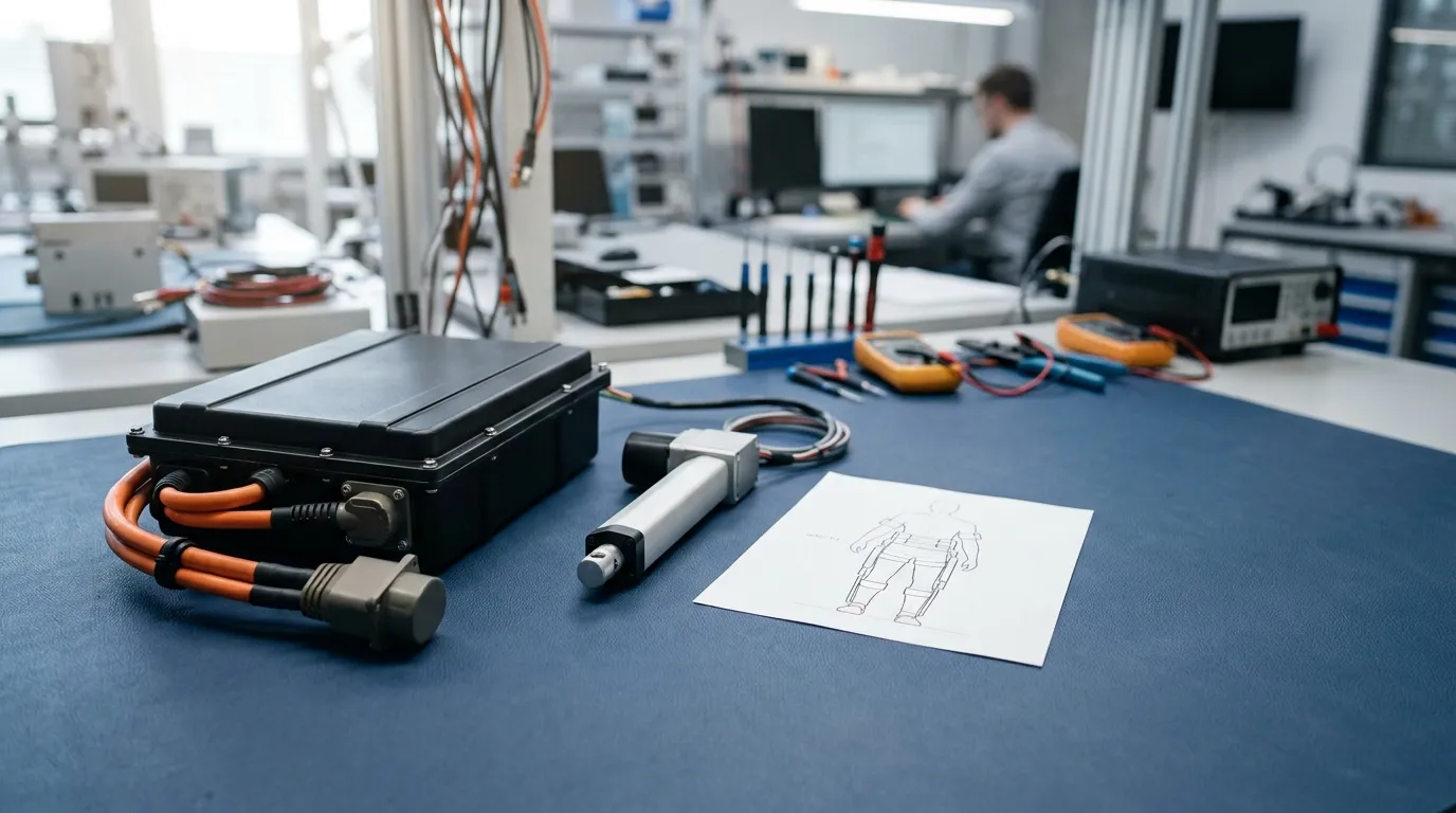
A custom battery pack for rehabilitation equipment is an application-specific rechargeable power solution engineered around the device's dynamic load profile, mechanical constraints, safety requirements, and documentation needs. Unlike off-the-shelf consumer batteries, a custom rehabilitation pack is designed so its chemistry, series/parallel configuration, battery management system (BMS), charger interface, enclosure, connector, and validation process all match how the equipment is actually used in clinical or home settings.
This guide explains how OEMs can translate rehabilitation equipment requirements into a battery pack specification, evaluate key design decisions, and work with a custom battery manufacturer through prototyping, validation, documentation, and production. For a broader overview of battery options across medical device categories, see our medical device battery pack solutions guide.
Why Rehabilitation Equipment Needs a Custom Battery Pack
Standard consumer batteries are rarely a good fit for rehabilitation equipment. Portable and wearable devices such as powered exoskeletons, continuous passive motion machines, mobility aids, and therapeutic stimulation devices have demanding electrical and physical requirements that generic power solutions cannot reliably meet.
Several factors drive the need for a custom design:
- Dynamic load profiles. Rehabilitation equipment often includes motors, actuators, and sensors that draw current in unpredictable patterns. A powered assistive device might require a low continuous current during idle monitoring but a high peak current during movement assistance.
- Physical integration constraints. Wearable and portable devices have strict limits on weight, thickness, and center of mass. A battery that fits a handheld medical monitor may be entirely unsuitable for a leg-mounted exoskeleton.
- Safety and protection requirements. The BMS must prevent overcharge, over-discharge, overcurrent, short circuit, and temperature extremes, but it must also avoid nuisance trips that interrupt therapy.
- Charging expectations. Patients, clinicians, or caregivers may charge the device overnight or between sessions. The pack and charger must work together reliably.
- Documentation and traceability. Medical-adjacent equipment often requires evidence of transport testing, material declarations, and batch traceability that consumer batteries simply do not provide.
When a standard pack fails on any of these points, the equipment manufacturer faces the cost of redesigning the product or managing field failures that are difficult to resolve.
Step 1: Define Your Equipment's Load Profile
The load profile — the electrical demand of your device over time — is the single most important input for battery pack design. It determines capacity, current capability, thermal behavior, and BMS settings. Without an accurate load profile, every downstream specification is guesswork.
Start by mapping the device's power consumption in each operating mode. Identify:
- Continuous current. The steady current draw during normal, sustained operation, such as a motor running at constant speed or control electronics staying active.
- Peak current. The maximum current draw during demanding events, such as motor startup, actuator movement under load, or simultaneous function activation.
- Peak duration. How long the peak current lasts. A 12 A draw for 200 milliseconds is very different from a 12 A draw for 10 seconds.
- Duty cycle. The ratio of active to idle time. A device that runs for 20 seconds and rests for 40 seconds has a significantly lower average demand than one that runs continuously.
- Idle and standby current. Power consumed while waiting for user input or maintaining settings.
These values directly affect battery capacity and cell selection. A pack sized only for the continuous current may experience rapid voltage sag or BMS shutdown when the actuator engages. A pack sized only for the peak current will be unnecessarily large, heavy, and expensive.
Record the load profile in a table with columns for operating mode, continuous current, peak current, peak duration, voltage requirement, and active time per cycle. This becomes the core of your battery specification and the basis for every calculation that follows.
Example: Estimating Capacity from a Load Profile
To estimate battery capacity, convert the load profile into an average current draw and multiply by the required runtime.
Example assumption: A powered mobility aid draws 3 A continuously and 10 A during movement-assist peaks of 5 seconds. The device operates at 24 V and must run for 6 hours per charge.
Step 1: Calculate the average current.
If the device draws 3 A continuously for 90% of the time and 10 A for 10% of the time:
- Average current = (3 A × 0.9) + (10 A × 0.1) = 2.7 A + 1.0 A = 3.7 A
Step 2: Calculate required capacity.
- Required capacity = Average current × Runtime = 3.7 A × 6 hours = 22.2 Ah
Step 3: Convert capacity to energy.
- Energy = Nominal voltage × Capacity = 24 V × 22.2 Ah = 532.8 Wh
Step 4: Add design margin.
Real-world factors such as temperature, aging, and internal resistance reduce usable capacity. Adding a 20% margin is common in preliminary estimates.
- Adjusted capacity = 22.2 Ah × 1.2 = 26.6 Ah
- Adjusted energy = 532.8 Wh × 1.2 = 639.4 Wh
This is a first-pass estimate, not the final pack specification. The actual value depends on the selected cell chemistry, allowed discharge depth, operating temperature, and BMS settings. However, it provides the starting point for cell selection and architecture design.
Step 2: Choose Cell Chemistry and Form Factor
Cell chemistry and physical format determine the pack's energy density, voltage profile, cycle life, temperature behavior, and safety characteristics. There is no universal "best" chemistry for rehabilitation equipment — the right choice depends on the device's requirements. For a deeper look at how lithium-based cells apply to medical device applications, see our guide on the lithium ion battery for medical devices.
| Chemistry | Nominal Cell Voltage | Energy Density | Typical Strengths | Typical Limitations | Best Fit When |
|---|---|---|---|---|---|
| Lithium-ion (Li-ion), cylindrical | 3.6–3.7 V | High | Mature supply chain; robust mechanical format; good energy density | Less flexible form factor; requires rigid enclosure or holder | Enclosure space is defined; high energy density needed; robust cells preferred |
| Lithium-polymer (LiPo), pouch | 3.7 V | High | Thin, shape-flexible; lightweight | Requires mechanical protection; swelling management needed | Weight and thickness matter; irregular enclosure shape |
| Lithium iron phosphate (LiFePO4) | 3.2 V | Moderate | Excellent thermal stability; longer potential cycle life | Lower energy density; higher volume and weight | Long service life and thermal stability are priorities; size is less critical |
| Nickel-metal hydride (Ni-MH) | 1.2 V | Moderate | Lower cost; well understood for legacy devices | Lower energy density; higher self-discharge | Replacing an existing Ni-MH pack in a legacy device |
Cylindrical Li-ion cells are the most common choice for medical and industrial battery packs because of their availability, consistency, and mechanical robustness. They handle vibration and impact well and are relatively easy to assemble into packs.
Pouch LiPo cells are preferred when the device enclosure is thin or irregularly shaped. They offer excellent energy density by weight but require a rigid enclosure to prevent swelling and physical damage.
LiFePO4 cells are useful when thermal stability and long service life matter more than size. Their lower nominal voltage (3.2 V per cell) means a higher series count for the same pack voltage, which increases complexity slightly.
For any chemistry selection, Gloflux and other custom battery manufacturers can engineer packs around the specific cell that matches the device's load profile and mechanical constraints. The cell choice is a starting point, not the final design decision.
Step 3: Design the Pack Architecture (Series and Parallel)
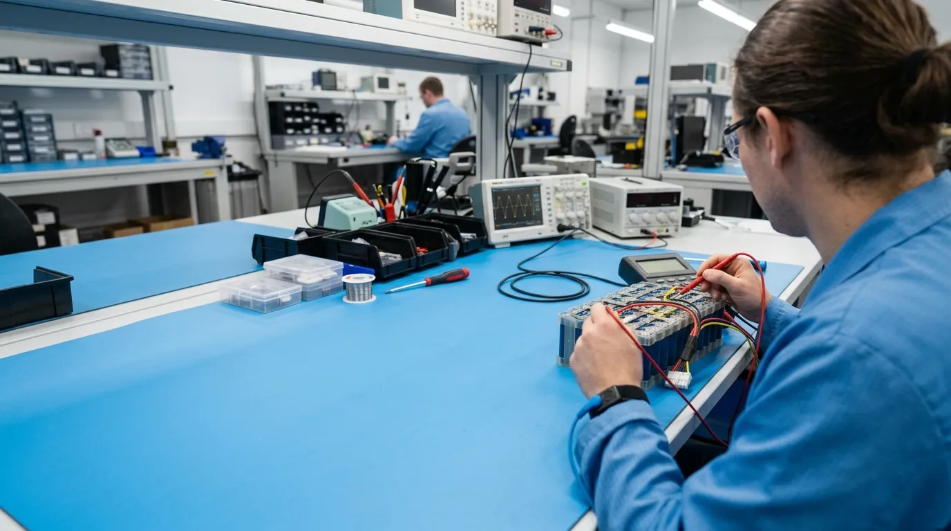
Battery pack architecture is described as a combination of series (S) and parallel (P) connections. This configuration determines the pack's nominal voltage, capacity, and current capability.
- Series connections (S) add voltage. Connecting cells in series increases the pack's nominal and maximum voltage. 2S configuration with Li-ion cells produces approximately 7.4 V nominal; 3S produces approximately 11.1 V; 4S produces approximately 14.8 V.
- Parallel connections (P) add capacity and current capability. Connecting cells in parallel increases the pack's total capacity in Ah and its ability to deliver higher current without excessive voltage sag.
For example, a pack labeled 3S/2P contains 3 cells in series to establish voltage and 2 parallel groups to double capacity. With 3.5 Ah cells at 3.7 V nominal, this pack would be approximately 11.1 V and 7.0 Ah, or about 77.7 Wh.
The architecture must be chosen with cell ratings in mind. A cell's datasheet specifies its maximum continuous and peak current. If the device requires 15 A peak but a single cell can safely deliver only 10 A, the pack needs additional parallel groups so the current is shared across cells.
The S/P configuration also affects BMS complexity. Higher series counts require balancing to keep all cells at similar charge levels, because small manufacturing differences between cells can lead to overcharge or undercharge over time.
Gloflux's custom battery pack lineup includes configurations from basic 1S designs through multi-series, multi-parallel arrangements, with the exact architecture determined by the device's voltage, capacity, and current requirements.
Step 4: Select Protection, BMS, and Charging Requirements
The battery management system governs how the pack behaves at its electrical limits. Choosing the right level of protection and monitoring is essential for rehabilitation equipment, where an unexpected shutdown can interrupt a therapy session.
Protection Circuit Module (PCM) vs. Battery Management System (BMS)
- A Protection Circuit Module (PCM) provides basic protection against overcharge, overdischarge, overcurrent, and short circuit. It is appropriate for simple packs where monitoring and communication are not required.
- A Battery Management System (BMS) adds monitoring and control functions on top of basic protection, including cell balancing, state-of-charge estimation, temperature monitoring, and sometimes communication interfaces.
- A Smart BMS extends this further with features such as fuel gauging, data logging, and communication protocols that allow the device to read remaining runtime or battery health.
For rehabilitation equipment, a BMS with balancing is strongly recommended whenever the pack has more than one cell in series. Without balancing, small differences in cell capacity or self-discharge can cause one cell to reach its limits before the others, reducing usable capacity and potentially leading to premature failure.
Nuisance Trip Prevention
Motorized rehabilitation equipment presents a specific challenge: the BMS may interpret a brief, high-current motor startup as a fault and disconnect the pack. This can happen when the BMS's overcurrent threshold is set too close to the device's normal peak current.
The solution is to define the peak current magnitude and duration explicitly in the battery specification, so the BMS can be configured to allow a short-duration overcurrent window without tripping. This is one of the most important details to communicate to your battery supplier.
Fuel Gauging and Communication
If the device needs to display remaining runtime or battery health, a fuel gauge is required. The gauge estimates state of charge by integrating current flow and accounting for the pack's voltage and temperature profile. Communication interfaces such as SMBus, I2C, UART, CAN, or Bluetooth support advanced monitoring and data retrieval — but the specific protocol must be agreed during design because it affects both BMS hardware and software.
Charger Compatibility
The charger must match the pack's chemistry, series count, charge voltage, and charge current limits. A charger designed for a different chemistry or S configuration can overcharge the pack, causing damage or creating a safety risk.
- Charge voltage must not exceed the pack's maximum charge voltage.
- Charge current must be within the pack's specified limit.
- The charger connector must have the correct polarity and physical fit.
- The charger and BMS must coordinate properly for charge termination.
Both the charger and the battery pack should be developed as one system to avoid mismatched behavior. If you are designing a rechargeable system, the same principles apply as those covered in our guide on the medical device rechargeable battery pack.
Step 5: Define Mechanical Integration, Enclosure, and Connectors
The mechanical design of the battery pack is just as important as the electrical design. Rehabilitation equipment is often worn on the body, moved frequently, or handled by patients with limited mobility — all of which impose specific physical demands.
Weight and Distribution
For wearable devices such as exoskeletons or powered orthoses, battery weight and placement directly affect comfort, balance, and energy consumption. The pack should be as light as the chemistry and capacity allow, and positioned to avoid negatively shifting the device's center of mass.
Enclosure
The enclosure protects cells, BMS, and wiring from physical impact, moisture, and dust. Considerations include:
- Rigidity. The enclosure must prevent deformation that could damage cells or short internal connections.
- Thermal management. Cells generate heat during discharge and charging. The enclosure should allow heat to dissipate, or include a thermal path to an external surface.
- Ingress protection. If the device may be exposed to moisture, an IP rating should be specified — but only if the enclosure is actually tested to that rating. "Water-resistant" is not the same as a verified IP rating.
- Vibration and shock. Movement, repeated handling, or transfer between surfaces can cause mechanical stress. The enclosure and internal cell mounting must withstand the expected environment.
Connectors and Wiring
The connector is the physical interface between the pack and the device, and between the pack and the charger. It must have the correct current rating, polarity keying, and locking mechanism. A connector rated for 5 A continuous will overheat if the device draws 12 A peak, even for a short duration.
Wiring must be sized for the expected current. Wire gauge (AWG) determines ampacity, and undersized wiring creates voltage drop and heat. Strain relief protects connections from repeated flexing.
Gloflux's custom battery pack design covers these integration elements, including wiring, connectors, casing, and assembly, working from the device's mechanical drawings and environment requirements.
Step 6: Prototype, Validate, and Transition to Production
A custom battery pack is only useful if it can be proven to meet the device's requirements. The development process should include distinct stages, each with clear acceptance criteria.
Prototype
The prototype verifies that the design works in practice. The OEM should check:
- Physical fit inside the device enclosure.
- Mechanical alignment of connectors and mounting points.
- Electrical performance against the load profile.
- BMS behavior during normal operation and fault conditions.
- Thermal behavior during representative current draw.
- Charger compatibility.
Validation Testing
Validation goes beyond functional testing to prove the pack meets the specified requirements over its intended life. A requirement-to-test matrix is the most useful tool for this stage. Each requirement in the battery specification is mapped to a specific test method, an acceptance criterion, and the evidence that will be recorded.
Common validation tests include:
- Capacity verification at defined charge and discharge conditions.
- Continuous and peak current testing.
- Cycle life testing under the device's duty cycle.
- Temperature performance within the operating range.
- Vibration and shock testing where relevant.
- Connector durability.
- Charger compatibility and charge termination.
The acceptance criteria must be defined before testing begins. "The pack should last long enough" is not a testable requirement. "The pack must deliver at least 90% of rated capacity after 300 full cycles under the specified test conditions" is testable and verifiable.
Pilot Run and Production
After prototype validation, a pilot run confirms the production process can produce consistent packs that meet the same specifications. The OEM should review:
- Cell batch traceability.
- Assembly consistency.
- Test data from production units.
- Quality control documentation.
- Change control procedures that require notification before any cell, BMS, connector, or process substitution.
Good change control is critical for medical and rehabilitation equipment. A seemingly minor cell substitution can change voltage behavior, current capability, or cycle life — and if it happens without notification, the OEM may unknowingly ship devices with different battery characteristics.
Documentation and Compliance: What to Request from Your Supplier
Battery documentation is often the difference between a smooth product launch and a regulatory or logistics problem. Before approving a pack design, request and review the following:
| Document | Purpose | What to Check |
|---|---|---|
| Datasheet or Technical Data Sheet (TDS) | Defines electrical, mechanical, and environmental specifications | Verify voltage, capacity, current, temperature range, dimensions, and test conditions |
| Safety Data Sheet (SDS/MSDS) | Documents hazards, handling, storage, and transport information | Confirm it matches the exact chemistry and construction |
| UN38.3 Test Summary | Supports lithium battery transport documentation | Verify the test summary covers the specific pack design, not just a similar model |
| Product Safety Test Reports | Evidence of testing to applicable standards such as IEC 62133 | Check the report scope includes the exact model and construction |
| Declaration Documents | CE, RoHS, REACH declarations where applicable | Confirm the legal entity and product scope |
| Quality System Certificate | Evidence of company-level quality management, such as ISO 9001 | Distinguish from product certification |
Transport Requirements for Lithium Batteries
Lithium cells and batteries offered for transport must have passed the design tests described in Section 38.3 of the UN Manual of Tests and Criteria. The U.S. Department of Transportation's Pipeline and Hazardous Materials Safety Administration (PHMSA) states that lithium cells and batteries must meet these testing requirements before being transported, and that manufacturers must make test summaries available upon request (PHMSA).
When shipped, lithium-ion batteries have specific UN classifications. A lithium-ion battery shipped alone is classified as UN 3480, while a lithium-ion battery contained in or packed with equipment is classified as UN 3481, according to IATA dangerous goods guidance. These classifications carry specific packing, labeling, and documentation obligations.
One of the most common misunderstandings is treating UN38.3 transport testing as equivalent to product safety certification. They are different evidence types. UN38.3 proves the battery survived defined transport simulation tests. A product safety standard such as IEC 62133 covers different safety characteristics and is scoped to the battery component, not the complete medical device.
Battery Standards vs. Medical Device Standards
For OEMs building medical or rehabilitation equipment, the distinction between battery-level and device-level compliance is critical. Battery standards such as IEC 62133 apply to the battery component itself. Medical electrical equipment standards such as IEC 60601-1 apply to the complete device, including how the battery integrates with the system. A battery that passes its own safety testing does not automatically make the completed medical device compliant.
The medical device manufacturer retains responsibility for system-level compliance, risk management, and any clinical validation required for the device's intended use. The same documentation and design rigor applies when developing packs for other medical equipment categories, such as a Custom battery pack for veterinary medical equipment, where equipment-specific durability and safety requirements are equally important.
How to Prepare an RFQ for a Rehabilitation-Equipment Battery Pack

A well-prepared request for quotation (RFQ) saves time and produces more accurate proposals. The battery supplier needs enough information to define the cell chemistry, S/P architecture, BMS, mechanical design, and documentation scope. Provide the following:
- Device description and application. Include the type of rehabilitation equipment and how it is used — wearable, portable, clinical, or home use.
- Load profile. Provide continuous current, peak current, peak duration, duty cycle, and operating modes.
- Target voltage and capacity. Specify nominal voltage, acceptable voltage range, and required runtime.
- Mechanical constraints. Provide the available enclosure space, maximum dimensions, weight limit, mounting requirements, and connector preferences.
- Environmental range. State the operating temperature range, storage temperature, and any ingress protection requirement.
- Charger requirements. Describe the charging method, expected charge time, and whether the charger is included in the project scope.
- Cycle life and lifetime. Define the expected number of charge/discharge cycles and the capacity retention threshold.
- Regulatory and documentation requirements. List the markets the device will be sold in and the documentation required for each.
- Volume and timeline. Provide annual quantity estimates and target production dates.
- Communication and monitoring needs. Describe any fuel gauge, data logging, or communication protocol requirements.
Including these details helps the supplier propose a pack that matches the device's actual requirements rather than a generic medical battery solution. Gloflux custom battery pack solutions cover cell selection, voltage design, BMS configuration, wiring, connectors, and casing, so a complete requirements package ensures the first proposal is relevant.
Final Words
A custom battery pack for rehabilitation equipment is not a commodity purchase. It requires mapping the device's dynamic electrical demand, selecting the right chemistry and form factor, designing an architecture that delivers the correct voltage and capacity, configuring a BMS that protects the pack without disrupting therapy, and validating the result with evidence the OEM can trust.
The most successful projects start with a clear requirement specification. Define your load profile, mechanical limits, charger expectations, and documentation needs before contacting a supplier. Then work with a custom battery manufacturer that can translate those requirements into a buildable, testable, and producible pack.
When you are ready to move forward, prepare your device requirements and discuss them with a custom battery pack manufacturer early — the earlier the engineering conversation starts, the fewer surprises you will encounter in prototyping and production.
Talk to the Manufacturer
Resources & Insights

High Capacity Lithium Battery for Wearables: High-Voltage LiPo Cell Design
2026-10-19

Cylindrical Battery Packs for Laptops: 2S vs 3S vs 4S Battery Design
2026-10-19

Stage Lighting Battery Pack: Prevent Voltage Drop & LED Flicker
2026-10-19

Best Rechargeable Batteries for Smart Devices: Performance, Safety, and Selection Guide
2026-10-19


