


 Home /
 Custom Lithium Battery for Portable Ultrasound Machines: OEM Power Solution


Table of Contents
- Why a Custom Battery Pack for Portable Ultrasound?
-
Defining Your Portable Ultrasound Battery Requirements
- Step 1: Define the Device Load Profile
- Step 2: Set the Runtime Target
- Step 3: Specify Voltage Requirements
- Step 4: Define Continuous and Peak Current
- Step 5: Define the Physical Envelope
- Step 6: Specify the Charging Interface
- Step 7: Define Environmental and Operating Conditions
- Step 8: Identify Documentation and Market-Access Requirements
- Choosing the Right Cell Chemistry and Form Factor
- Electrical Design of the Ultrasound Battery Pack
- Battery Management System (BMS) and Protection
- Charging the Ultrasound Battery Pack
- Mechanical Design and Thermal Management
- Prototype, Validation, and Production
- Testing and Documentation: What the Supplier Should Provide
- Sourcing and RFQ Checklist
- Common Problems to Avoid
- Portable Ultrasound and Other Handheld Diagnostic Devices
- Conclusion

A custom lithium battery for portable ultrasound machines is a rechargeable battery pack engineered around the specific voltage, energy, current, mechanical, thermal, and documentation requirements of an ultrasound system. Unlike a generic off-the-shelf battery, a custom pack is designed from the device's load profile, runtime target, physical enclosure, charging interface, and applicable safety and transport standards — which is why medical device OEMs typically need a tailored medical device rechargeable battery pack rather than a standard catalog product.
For OEMs developing portable ultrasound systems, the battery is a critical subsystem that directly affects runtime, weight, clinical workflow, and regulatory documentation. Getting the specification right early reduces project risk. This guide walks through the complete engineering-to-procurement process for a custom portable ultrasound battery — from defining requirements through supplier evaluation.
For broader context on batteries used across medical devices, see our lithium ion battery for medical devices guide.
Why a Custom Battery Pack for Portable Ultrasound?
Portable ultrasound devices place demands on a battery that standard consumer or industrial packs rarely satisfy. The device's load profile is typically a combination of sustained imaging operation, periodic high-current bursts, standby power for sensors or displays, and occasional peak loads during startup or probe operation. Each of these phases affects the battery's required capacity, continuous current rating, peak current capability, and voltage stability.
A standard pack usually fails on at least one of these dimensions:
- Voltage mismatch. The pack's nominal and full-charge voltage may not align with the device's power architecture.
- Insufficient current capability. The pack may sag under the device's peak load, causing resets or unstable imaging.
- Mechanical incompatibility. The enclosure, connector, mounting points, or cable routing may not fit the device.
- Charger coordination. The pack's chemistry and series configuration must match the charger's voltage and current profile.
- Documentation gaps. Medical device OEMs typically need model-specific test summaries, transport documentation, and traceability — which off-the-shelf batteries may not provide.
A custom design addresses these issues by starting from the device's actual requirements rather than forcing a standard product to fit.
Defining Your Portable Ultrasound Battery Requirements
Before approaching a battery supplier, define the requirements that will drive the pack design. The more complete this specification, the more accurate the feasibility assessment, quotation, and prototype timeline.
Step 1: Define the Device Load Profile
The load profile describes how much power the ultrasound system draws during each operating phase. The battery supplier needs to understand:
- Average continuous load — typical power draw during normal imaging or scanning.
- Peak load — maximum power during startup, probe activation, or high-intensity modes.
- Standby load — power draw when the device is idle but powered on.
- Duration of each phase — how long the device operates in each state.
This load profile determines the pack's energy requirement (for runtime) and its current capability (for stable voltage under load).
Step 2: Set the Runtime Target
The runtime target is the minimum operating time the device must deliver under a defined load. It is typically expressed in hours and tied to a clinical workflow — for example, continuous scanning, intermittent use, or a full shift.
Runtime, together with the average load, determines the pack's energy requirement in watt-hours (Wh). A simple relationship applies:
Energy (Wh) = Average Power (W) × Runtime (h)
The battery supplier also needs to know how much of the pack's theoretical energy can be used before the device shuts down. This depends on the cutoff voltage and the discharge profile — both of which should be defined in the specification.
Step 3: Specify Voltage Requirements
The nominal voltage of the pack must match the device's input range. The series cell count (S count) determines this voltage. For example:
- A single lithium-ion cell has a nominal voltage of approximately 3.6–3.7 V and a maximum charge voltage of 4.2 V.
- A 3S configuration provides a nominal voltage of approximately 10.8–11.1 V and a full-charge voltage of 12.6 V.
- A 4S configuration provides a nominal voltage of approximately 14.4–14.8 V and a full-charge voltage of 16.8 V.
It is essential to distinguish nominal voltage (the average voltage during discharge) from maximum charge voltage (the voltage the charger applies). The device's power architecture must accept both.
Step 4: Define Continuous and Peak Current
Continuous current is the sustained current the pack must deliver during normal operation. Peak current is the short-duration maximum the pack must handle without excessive voltage sag or protection-circuit activation.
For a portable ultrasound device, the peak current can be significantly higher than the average — for example, during probe operation or mechanical startup. The battery supplier needs both values, plus the duration of the peak.
The relationship between current and capacity is often expressed as a C-rate. A 1C rate means the current equals the pack's capacity in ampere-hours. A 2C rate means the current is twice the capacity. The correct C-rate depends on the device's actual current draw, not a generic assumption.
Step 5: Define the Physical Envelope
The pack must fit inside the device's enclosure. Specify:
- Maximum dimensions (length, width, height).
- Available volume and any irregular shapes.
- Mounting method (screws, clips, adhesive, or tool-free replacement).
- Connector type and orientation.
- Cable routing and wire length.
- Weight limit.
For handheld ultrasound probes, the pack must be compact and lightweight. For portable carts, the pack may have more space but may need higher energy density.
Step 6: Specify the Charging Interface
The charger must match the pack's chemistry and series configuration. Define:
- Charging method (external charger, onboard charging circuit, or USB-C).
- Charging voltage and current.
- Charging time target.
- Whether the battery can be charged while the device is in use.
The charger's output voltage must never exceed the pack's maximum charge voltage. The battery supplier can help confirm compatibility once the design is specified.
Step 7: Define Environmental and Operating Conditions
Portable ultrasound devices may operate across a range of temperatures, humidity levels, and physical environments. Specify:
- Operating temperature range (charging and discharging may have different limits).
- Storage temperature range.
- Humidity or moisture exposure.
- Shock, vibration, and drop requirements.
- Any sealing or ingress protection requirement.
These conditions affect cell selection, enclosure design, and thermal management.
Step 8: Identify Documentation and Market-Access Requirements

Medical device OEMs typically need a defined documentation package from the battery supplier. This may include:
- Model-specific test reports or certificates (where applicable to the battery as a component).
- A UN 38.3 test summary for lithium battery transport.
- SDS/MSDS documentation.
- Declaration or conformity documents required for the target market.
- Traceability records for cells and production lots.
The exact documentation depends on the device's target markets and the battery's construction. The supplier should confirm what they can provide for the specific model, not a general company-wide list.
Choosing the Right Cell Chemistry and Form Factor
The cell chemistry and form factor are among the first design decisions. Each option has trade-offs that must be evaluated against the device's requirements.
| Feature | Li-ion (Cylindrical) | LiPo (Pouch) | LiFePO4 (Cylindrical/Pouch) |
|---|---|---|---|
| Nominal cell voltage | ~3.6–3.7 V | ~3.7 V | ~3.2 V |
| Energy density | High | High | Moderate |
| Form flexibility | Rigid, cylindrical | Thin, flexible shapes | Rigid or pouch |
| Mechanical robustness | High | Lower; requires enclosure support | High |
| Cycle life | Good | Moderate | Excellent |
| Safety profile | Good with protection | Good with protection; swelling risk | High |
| Typical use | High-energy, robust packs | Thin devices, compact designs | High-cycle, safety-critical applications |
| Swelling risk | Low | Moderate; must be designed for | Low |
| Cost | Moderate | Higher for complex shapes | Higher per Wh in some cases |
For a handheld ultrasound probe, a LiPo pouch cell may be preferred for its thin profile and ability to fill an irregular enclosure. However, the design must accommodate potential swelling over the pack's life.
For a portable ultrasound cart, cylindrical Li-ion cells may offer better mechanical robustness, simpler thermal management, and a proven supply chain.
LiFePO4 is a reasonable choice only when the system can accept a lower nominal voltage (requiring more cells in series for the same pack voltage) and a lower energy density. Its advantages — long cycle life and high safety tolerance — may matter for certain applications.
The correct choice depends on the device's envelope, energy requirement, current profile, charging time, and expected service life. There is no universal best chemistry for portable ultrasound.
Electrical Design of the Ultrasound Battery Pack
Series and Parallel Configuration
The pack's electrical architecture is defined by its series and parallel configuration.
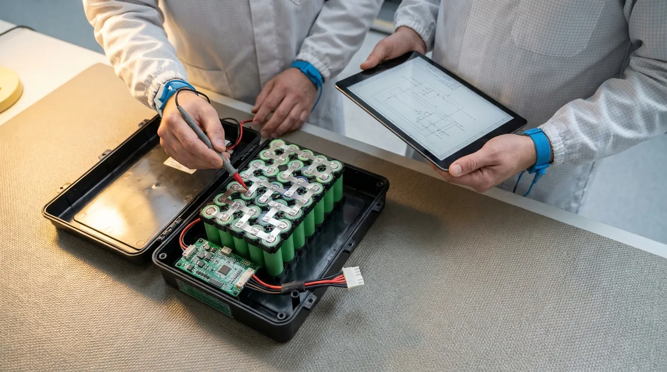
Series cells (S count) add voltage. Three cells in series (3S) deliver three times the nominal cell voltage. Four cells in series (4S) deliver four times the nominal voltage.
Parallel cells (P count) add capacity and current capability. Two cells in parallel (2P) double the capacity and can deliver more current than a single cell.
For example, a 3S2P configuration contains six cells: two parallel groups of three series-connected cells. The pack's nominal voltage is determined by the series count; the capacity and current capability are influenced by the parallel count.
The correct configuration balances voltage, capacity, current, physical space, and thermal behavior. It cannot be chosen without the device's load profile and enclosure constraints.
Voltage, Capacity, and Energy
- Nominal voltage is the average voltage during discharge.
- Maximum charge voltage is the highest voltage the charger applies.
- Capacity (mAh or Ah) describes the total charge the pack can deliver.
- Energy (Wh) is the product of capacity and voltage, and is the more meaningful measure when comparing packs of different voltages.
These values must not be confused. A pack with a higher capacity but lower voltage may deliver less total energy than a lower-capacity pack with a higher voltage.
Continuous Current vs. Peak Current
A battery pack has two current ratings:
- Continuous current — the current the pack can deliver indefinitely without exceeding its thermal or electrical limits.
- Peak current — the maximum current the pack can deliver for a short duration, typically limited by the BMS or cell characteristics.
For an ultrasound device, the peak current may occur during startup or probe operation. If the pack's peak rating is too low, the BMS may trip or the voltage may sag below the device's operating threshold.
Voltage Sag
Voltage sag is the temporary drop in pack voltage under load. It is caused primarily by the pack's internal resistance. When the device draws a high current, the voltage at the pack terminals falls.
If the voltage sag is large enough, the device may reset, shut down, or exhibit unstable imaging. The battery supplier must know the device's minimum acceptable voltage under load to ensure the pack has sufficient current capability and acceptably low internal resistance.
Battery Management System (BMS) and Protection
The BMS or protection circuit monitors the pack and limits operation to safe conditions. Its scope depends on the pack design and the device's requirements.
Basic Protection (PCM)
A basic protection circuit module (PCM) protects against:
- Overcharge.
- Over-discharge.
- Overcurrent.
- Short circuit.
A PCM is a simple safety layer. It does not typically provide balancing, communication, or state-of-charge reporting.
Smart BMS
A smart BMS adds more intelligence:
- Cell balancing — equalizes voltage across series cells, improving consistency and usable life.
- Fuel gauging — estimates state of charge and remaining runtime.
- Communication — supports protocols such as SMBus, I²C, UART, CAN, RS485, or Bluetooth (depending on the model and the device's host interface).
- Data logging — records charge/discharge history for diagnostics.
Not every pack requires a smart BMS. The decision depends on the device's need for accurate runtime reporting, balancing across multiple series cells, and communication with the host system.
BMS Protection Thresholds
The BMS thresholds — charge voltage, discharge cutoff, current limits, and temperature limits — must be configured for the pack's chemistry and cell configuration. These thresholds must align with the charger and the device's operating range.
The complete custom battery pack design (inferred) process covers BMS selection and integration in detail.
Charging the Ultrasound Battery Pack
The charging system must be matched to the pack's chemistry and series configuration.
Charging Profile
Most lithium-ion and LiPo cells use a CC-CV (constant current, constant voltage) charging profile. The charger applies a constant current until the cell reaches its maximum charge voltage, then holds that voltage while the current tapers down.
The charger's output voltage must not exceed the pack's maximum charge voltage. The charge current must be within the cells' rated limits.
Charger Compatibility
The OEM must confirm that the charger is compatible with the pack. Key parameters include:
- Maximum charge voltage.
- Charge current.
- Charge termination method.
- Charging temperature range.
If the device charges the battery internally, the charging circuit is part of the device's power architecture. If the battery is charged externally, the pack connector and the charger must be mechanically and electrically matched.
Fast Charging
If fast charging is required, the cells and BMS must be designed for it. Faster charging typically generates more heat and may reduce cycle life. The trade-off must be evaluated against the device's workflow.
Mechanical Design and Thermal Management
Connector and Wiring
The connector must match the device's interface in terms of:
- Pin count and polarity.
- Current rating.
- Mechanical retention.
- Keying to prevent reverse insertion.
The wiring gauge must be adequate for the continuous and peak current. Undersized wiring can overheat and create a voltage drop under load.
Enclosure Design
The enclosure protects the cells and provides mechanical support. For a portable ultrasound device, the enclosure must:
- Fit within the device's available space.
- Provide structural support for cells and connections.
- Manage heat from the cells and the device.
- Resist shock, vibration, and drop impact.
- Meet any ingress protection (IP) requirement.
The IP rating is a specific standard that defines protection against solids and liquids. It should not be described as generic "waterproof" unless the specific rating supports it.
Thermal Management
Lithium-ion cells generate heat during discharge and charging. In a compact enclosure, heat may accumulate and cause:
- Reduced performance.
- Accelerated aging.
- In extreme cases, safety risk.
The pack design must include a thermal path to dissipate heat. This may involve:
- An aluminum or thermally conductive enclosure.
- Thermal interface materials (TIM) between cells and enclosure.
- Airflow provisions in the device.
- BMS temperature monitoring and derating.
The thermal design is especially important for a handheld ultrasound probe, where the battery is close to the user and the enclosure is sealed.
Prototype, Validation, and Production
Prototype
A prototype validates the pack design before tooling for mass production. The prototype should confirm:
- Mechanical fit.
- Electrical performance.
- BMS behavior.
- Charger compatibility.
- Thermal behavior under load.
The OEM should review the prototype against the original specification and provide feedback on fit, function, and performance.
Validation Testing
Validation testing confirms the pack meets the design requirements. It may include:
- Capacity testing.
- Cycle-life testing.
- Load testing under continuous and peak current.
- Temperature testing across the operating range.
- Vibration, shock, and drop testing.
- Charger compatibility testing.
- BMS function verification.
The test plan should be agreed between the OEM and the battery supplier before prototyping begins.
For a detailed walkthrough of the broader design and manufacturing process, see our guide on custom battery pack design.
Testing and Documentation: What the Supplier Should Provide
Medical device OEMs need to distinguish between the battery component's evidence and the complete device's compliance. The battery is a component; the ultrasound device is a medical device with its own regulatory obligations.
UN 38.3 Transport Testing
For lithium batteries shipped by air, rail, road, or sea, manufacturers must provide a test summary according to the UN Manual of Tests and Criteria, Section 38.3. The tests include altitude simulation, thermal cycling, vibration, shock, external short circuit, impact, overcharge, and forced discharge, depending on the cell or battery construction.
The UN 38.3 test summary is a transport document, not a product-safety certificate. It does not prove that the battery is safe to use in a medical device. The U.S. Department of Transportation's Pipeline and Hazardous Materials Safety Administration (PHMSA) provides guidance on lithium battery transport documentation (PHMSA lithium batteries), and the UN test summary requirement applies to cells and batteries manufactured after specific dates, depending on the transport mode.
IEC and UL Testing
IEC 62133 covers safety testing for rechargeable cells and batteries used in portable applications. UL standards, such as UL 2054, also apply to household and commercial batteries. These are product-safety standards, distinct from UN 38.3 transport testing.
Whether IEC 62133 or a UL standard applies depends on the battery's construction, target market, and the requirements of the device OEM. The battery supplier should confirm exactly which standard, edition, and scope applies to the specific pack — and provide the corresponding report or certificate.
It is important to distinguish battery-component testing from complete-medical-device compliance. A battery that passes IEC 62133 or UN 38.3 is not a certified medical device.
Documentation Checklist
The OEM should request a documentation package that includes, where applicable:
- Model-specific datasheet (TDS) with specifications and test conditions.
- UN 38.3 test summary for transport.
- SDS/MSDS.
- IEC/UL report or certificate, if claimed.
- Declaration or conformity documents for the target market.
- Traceability records for cells and production lots.
The supplier should confirm the legal entity, model scope, standard edition, issuing body, and validity of any certificate or report. A general company-level certification list is not sufficient evidence for a specific pack.
Sourcing and RFQ Checklist
Before sending an RFQ to a battery supplier, prepare a complete requirements document. The following checklist covers the data the supplier needs to provide an accurate feasibility assessment and quotation.
Electrical Requirements
- Nominal voltage.
- Minimum and maximum input voltage range of the device.
- Average continuous current or power.
- Peak current and duration.
- Runtime target under a defined load.
- Charging method and target charge time.
Energy and Capacity
- Runtime target in hours.
- Average load in watts.
- Usable energy required (Wh).
- Capacity required (Ah), based on the pack voltage and cutoff voltage.
Mechanical Requirements
- Maximum dimensions.
- Available volume and shape constraints.
- Mounting method.
- Connector type and pinout.
- Cable length and routing.
- Weight limit.
Environmental Requirements
- Operating temperature range (charging and discharging).
- Storage temperature range.
- Humidity or moisture exposure.
- Shock, vibration, and drop requirements.
- IP rating, if required.
BMS and Communication
- Protection requirements (PCM vs. BMS).
- Balancing requirement.
- Fuel gauge requirement.
- Communication protocol (only if the device supports it).
- State-of-charge reporting requirement.
Documentation and Quality
- Testing and validation requirements.
- UN 38.3 test summary requirement.
- IEC/UL report/certificate requirement.
- SDS/MSDS requirement.
- Traceability requirement.
- Change-notification requirement.
Commercial and Development Requirements
- Prototype quantity and timeline.
- Sample approval process.
- Tooling and NRE requirements.
- MOQ and lead time.
- Quality agreement and warranty.
The more clearly these requirements are defined, the faster the supplier can respond and the more accurate the quotation will be.
Common Problems to Avoid
Voltage Sag and Device Resets
When the battery's current capability is insufficient, or the internal resistance is too high, the pack voltage can sag below the device's minimum under load. This can cause resets or unstable imaging. Specify the peak current correctly, and confirm the pack can support it.
BMS Trips
A BMS that is incorrectly configured can trip during normal operation. Protection thresholds must be set above the device's maximum expected current and voltage, with adequate margin.
Cell Imbalance and Premature Aging
Series cells must be closely matched for capacity, voltage, and internal resistance. Unmatched cells can lead to imbalance, reduced capacity, and premature failure — especially in packs with multiple series cells.
Thermal Issues
A sealed enclosure with high current draw can cause heat buildup, leading to reduced performance and accelerated aging. The thermal design must be validated under worst-case load conditions.
Documentation Gaps
A battery supplier that cannot provide model-specific transport and test documentation delays the device's market launch. Confirm the documentation package before production.
Counterfeit or Inconsistent Cells
Using untraceable or counterfeit cells is a serious safety and reliability risk. The supplier should be able to demonstrate cell sourcing and traceability.
Portable Ultrasound and Other Handheld Diagnostic Devices
The same requirements-driven approach applies to other handheld diagnostic devices, where envelope, weight, and runtime are critical. For a comprehensive discussion of batteries for compact diagnostic equipment, see our guide on Rechargeable battery for handheld diagnostic devices.
Conclusion
A custom lithium battery for a portable ultrasound machine is not a single catalog product — it is a designed subsystem. The correct pack starts with a clear definition of the device's load profile, voltage, current, runtime, mechanical envelope, and charging environment. From that specification, the supplier selects the chemistry and cell format, designs the S/P architecture, configures the BMS, and validates the pack through prototyping and testing.
For medical device OEMs, the documentation package is as important as the electrical design. Model-specific test reports, a UN 38.3 transport summary, SDS/MSDS, and traceability records are essential for market access and long-term reliability.
When you are ready to evaluate a battery partner, send a complete requirements document — with your load profile, runtime target, voltage and current specifications, mechanical constraints, and documentation needs. The more complete your specification, the faster a supplier can confirm feasibility and deliver a viable prototype.
Talk to the Manufacturer
Resources & Insights

High Capacity Lithium Battery for Wearables: High-Voltage LiPo Cell Design
2026-10-19

Cylindrical Battery Packs for Laptops: 2S vs 3S vs 4S Battery Design
2026-10-19

Stage Lighting Battery Pack: Prevent Voltage Drop & LED Flicker
2026-10-19

Best Rechargeable Batteries for Smart Devices: Performance, Safety, and Selection Guide
2026-10-19


