


 Home /
 Lithium Battery for Portable Blood Analyzers: OEM Runtime and Pack Design


Table of Contents
- Step 1 — Capture the Portable Blood Analyzer's Load Profile
- Step 2 — Calculate Runtime Requirements and Battery Energy
- Step 3 — Define Voltage, Capacity, and Pack Architecture
- Step 4 — Choose the Right Protection and Battery Management
- Step 5 — Match the Charger, Connector, and Charging Interface
- Step 6 — Fit the Pack into the Analyzer's Mechanical Envelope
- Step 7 — Validate Performance, Safety, and Documentation
- Step 8 — Ask the Right Supplier Questions (RFQ Checklist)
- Final Thought — Power the Analyzer, Not a Guess
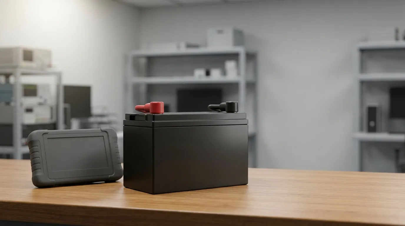
A lithium battery for a portable blood analyzer must be engineered as a custom power system based on the device's measured voltage requirements, load profile, target runtime, mechanical envelope, charging interface, and required safety documentation — not selected as a generic off-the-shelf pack. For medical device OEMs, the pack design process starts by capturing how the analyzer actually draws current across its operating states, then translates that data into a validated battery specification. This guide walks through that engineering process from load profile to supplier RFQ, with a focus on runtime accuracy and reliable pack design.
Step 1 — Capture the Portable Blood Analyzer's Load Profile
The first step in designing a battery pack for a portable blood analyzer is understanding exactly how the device consumes power. A blood analyzer rarely draws a constant current. Instead, it typically operates in several distinct states, each with different electrical demands.
Common operating states include:
| Analyzer State | Typical Function | Current Draw | Duration | Duty Cycle |
|---|---|---|---|---|
| Startup | Microcontroller boot, sensor initialization | Higher transient | Seconds | One-time |
| Measurement/assay cycle | Sample processing, optical or electrochemical sensing | Moderate continuous | Seconds to minutes | Repeating |
| Internal heating or pumping | Temperature control, fluid movement | High continuous | Variable | As required |
| Display and backlight | User interface | Low continuous | Entire operation | Always on |
| Wireless/communication | Data transfer | Intermittent bursts | Short | Occasional |
| Standby/idle | Awaiting next test | Very low | Long duration | Dominant |
By estimating or measuring the current draw and duration for each state, you can calculate two critical values:
- Average load — the current drawn over a full operating cycle, used for runtime estimation.
- Peak load — the highest transient current, used to verify the pack's maximum discharge capability.
The distinction matters because a pack sized only for average current may fail during startup, heating, or pumping; a pack sized only for peak current may be larger and more expensive than necessary. Both figures must be captured before any cell or pack selection begins.
Step 2 — Calculate Runtime Requirements and Battery Energy
Runtime for a portable blood analyzer is determined by the pack's usable energy in watt-hours (Wh), not simply by its capacity in milliamp-hours (mAh). Energy accounts for both voltage and charge capacity:
Energy (Wh) = Nominal Voltage (V) × Capacity (Ah)
For example, a 7.4V pack with 5.0Ah capacity stores 37Wh of energy. The same 5.0Ah capacity at 3.7V stores only 18.5Wh. Runtime must therefore be calculated using energy, not capacity alone.
To estimate required energy:
- Define the operating cycle — how the analyzer moves through measurement, standby, communication, and other states during a typical use session.
- Multiply each state's current by its duration and voltage to obtain the energy consumed per state.
- Sum the state energies to find energy per full operating cycle.
- Add practical derating factors — typically for temperature extremes, battery aging over service life, and a safety reserve so the analyzer never shuts down mid-measurement.
- Divide target runtime by cycle energy to determine the minimum pack energy required.
Important caveat: the usable energy of a lithium pack is not the full rated energy. The device's low-voltage cutoff determines how much of the pack's stored energy can actually be delivered. A device that cuts off at a higher voltage will leave more energy unused.
Step 3 — Define Voltage, Capacity, and Pack Architecture
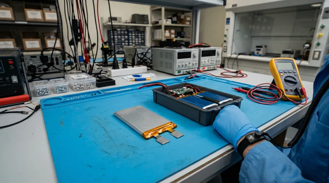
A lithium battery pack is built from individual cells arranged in series and parallel. This architecture, written as S/P configuration, determines the pack's electrical characteristics.
How Series and Parallel Cells Work
| Configuration Element | What It Determines | Example |
|---|---|---|
| Series cells (S) | Adds voltage | Two 3.7V cells in series = 7.4V nominal |
| Parallel cells (P) | Adds capacity/current | Two 2.5Ah cells in parallel = 5.0Ah |
The correct configuration depends entirely on the analyzer's requirements:
- Device input voltage defines the required series count.
- Runtime and load current define the required parallel count and cell capacity.
- Maximum charge voltage must match the charger and the device's charging circuit.
For one analyzer, a 2S2P configuration might be appropriate; for another, a 4S1P arrangement may fit the voltage and mechanical envelope better. Gloflux publishes a pack configuration range of 1S–6S and 1P–nP with pack voltages from 3.7V to 24V across its battery pack product range. Do not copy a configuration from another analyzer design; the series and parallel counts must follow from your device's actual voltage and load requirements.
Cell Chemistry and Form-Factor Selection
Chemistry selection involves balancing energy density, physical size, cycle life, temperature tolerance, and safety.
| Chemistry | Strengths | Limitations | Best Fit |
|---|---|---|---|
| Lithium-ion (NMC/INR-style) | High energy density, mature supply chain | Requires protection; moderate cycle life | Compact analyzers where runtime per gram matters |
| Lithium-polymer (LiPo) | Thin, flexible form factors; good energy density | Requires careful mechanical and charge protection | Analyzers with unusual or tight internal geometry |
| Lithium iron phosphate (LiFePO4) | Long cycle life, improved thermal stability | Lower energy density; higher volume/weight | Analyzers where cycle life or thermal robustness outweighs compactness |
Form factor matters as much as chemistry. Cylindrical cells offer mechanical robustness and standardized manufacturing. Prismatic and pouch cells allow thinner or more space-efficient designs. For a deeper look at how chemistry choices apply across medical equipment, see our guide to lithium ion battery for medical devices. Gloflux's medical device battery solutions cover cylindrical, prismatic, and lithium-polymer configurations customized around the device size, voltage, and discharge rate.
There is no universal "best" chemistry for a portable blood analyzer. The correct choice depends on whether the design prioritizes runtime density, physical fit, cycle life, or operating temperature range.
Step 4 — Choose the Right Protection and Battery Management
Every lithium battery pack requires protection electronics. The two main approaches are a basic protection circuit module (PCM) and a battery management system (BMS).
| Feature | Basic PCM | Smart BMS |
|---|---|---|
| Overcharge protection | Yes | Yes |
| Over-discharge protection | Yes | Yes |
| Overcurrent protection | Yes | Yes |
| Short-circuit protection | Yes | Yes |
| Temperature monitoring | Often limited | Yes, with charge/discharge limits |
| Cell balancing | No | Yes (multi-series packs) |
| Fuel gauging / state of charge | No | Yes |
| Communication (SMBus, I²C, etc.) | No | Optional |
| Data logging / state of health | No | Optional |
For a portable blood analyzer, the decision between PCM and smart BMS depends on several factors:
- Multi-series packs benefit from cell balancing to maintain consistency over time.
- Runtime displays require a fuel gauge to estimate remaining charge accurately.
- Thermal safety is improved with temperature sensing that can halt charge or discharge outside safe limits.
- Communication with the analyzer's main processor may be desired for status reporting, but only if the pack and device both support the protocol.
A basic PCM may be sufficient for a simple single-series pack. A smart BMS becomes valuable when the analyzer needs accurate runtime reporting, balancing across multiple series cells, or communication with the host device.
Gloflux states that its medical battery systems include BMS monitoring of voltage, temperature, and current. Confirm the exact BMS features with the supplier for your specific pack configuration and analyzer requirements.
Step 5 — Match the Charger, Connector, and Charging Interface
The charger is part of the battery system, not an afterthought. An incorrect charger can overcharge a pack, reduce cycle life, or create a safety hazard.
Charger compatibility requires matching:
| Parameter | What Must Match |
|---|---|
| Chemistry | Li-ion, LiPo, and LiFePO4 have different charge profiles |
| Series count | Charge voltage rises with each series cell |
| Charge current | Must respect the cell manufacturer's recommended limits |
| Temperature limits | Charging should halt outside the rated temperature range |
Most lithium packs use a constant-current/constant-voltage (CC/CV) charging profile. The charger applies a fixed current until the pack reaches its maximum charge voltage, then holds that voltage while current tapers to a termination threshold. Exceeding the maximum charge voltage for the series count is a common cause of pack failure.
The connector and wiring are equally important. The connector must handle the charge and discharge current, maintain correct polarity, and withstand repeated connection cycles. Wiring gauge must be sized for the current without excessive voltage drop.
For a portable blood analyzer, also consider whether the pack is charged inside the device through a medical device rechargeable battery pack architecture or removed for external charging. USB-C charging is possible only if the pack, BMS, and device all support the necessary power-delivery negotiation.
Step 6 — Fit the Pack into the Analyzer's Mechanical Envelope
The electrical design is only half of the pack specification. The physical design must fit the analyzer's internal space, protect the cells and electronics, and manage heat.
Mechanical Specification Checklist
| Parameter | Consideration |
|---|---|
| Pack dimensions | Must fit the allocated internal volume with clearance |
| Weight | Affects portability and handling |
| Enclosure material | Provides structural protection and electrical insulation |
| Cell mounting | Cell holders, insulation, busbars, and welding points |
| Thermal path | Heat removal during charging and peak discharge |
| Connector placement | Accessible for assembly and service |
| Cable routing | Avoids pinching or abrasion |
| Ingress protection | Only if the analyzer environment requires it (e.g., IP-rated enclosures) |
Temperature management deserves special attention. Heat generated during high-current discharge or fast charging must be conducted away from cells. Conversely, the pack must operate when the analyzer is used in cold environments. The enclosure and thermal design must support both extremes.
The mechanical integration principles for a blood analyzer follow the same design logic used for other compact diagnostic tools. For broader guidance on physical pack design in portable diagnostics, see our guide to rechargeable battery for handheld diagnostic devices.
Mechanical validation typically includes drop, vibration, and shock testing appropriate to how the analyzer is handled in clinical or field use. These tests confirm that cells, BMS, and connections survive real-world conditions.
Step 7 — Validate Performance, Safety, and Documentation
Before accepting a custom battery pack, the OEM must verify that it meets the device's electrical, mechanical, and documentation requirements. This step protects both the device and the end user.
Performance Validation
| Test | What It Confirms |
|---|---|
| Capacity test | Delivered capacity at stated current and temperature |
| Runtime test | Actual runtime under the device's real load profile |
| Continuous current test | Sustained current capability |
| Peak current test | Transient current handling during startup or peak loads |
| Charge test | Correct CC/CV behavior and termination |
| Cycle test | Capacity retention over stated cycles with defined conditions |
| Temperature test | Operation within the device's environmental range |
Documentation: What Each Document Actually Proves
| Document | Purpose | Scope/Limitation |
|---|---|---|
| Datasheet/TDS | Describes the product's published specifications | Model-specific; verify conditions |
| SDS/MSDS | Safety data for handling, storage, and transport | Not a product-safety certification |
| UN 38.3 test summary | Supports transport of lithium batteries | Confirms tested product-and-test reference, not general product approval |
| IEC/UL/CB report | Product-safety testing for the defined model | Applies to the exact construction and standard scope tested |
| Device-level approval | Medical-device regulatory compliance | OEM responsibility; battery evidence alone does not establish it |
Two documents are commonly confused. A UN 38.3 test summary verifies that a lithium battery has passed the UN transport tests (T1–T8) — altitude simulation, thermal cycling, vibration, shock, external short circuit, impact/crush, overcharge, and forced discharge. It documents that the battery may be shipped under applicable dangerous-goods rules. An IEC 62133 or UL safety report, by contrast, evaluates the product against a defined safety standard for portable sealed lithium cells and batteries. These are different documents with different purposes.
A battery used in medical equipment is also not automatically a certified medical device. The battery component's safety evidence is separate from the complete analyzer's regulatory approval, which remains the OEM's responsibility.
Gloflux provides customization around device size, voltage, discharge rate, and operating conditions for medical battery systems. When evaluating any supplier, ask for the specific model's datasheet, test reports, and documentation rather than accepting a general company-level statement.
Step 8 — Ask the Right Supplier Questions (RFQ Checklist)

When you are ready to evaluate a custom battery supplier, use this checklist to ensure you receive complete and verifiable information:
Battery Specification
- Exact cell manufacturer and cell model
- Cell datasheet with original test conditions
- Pack nominal voltage, capacity, and energy (Wh)
- Continuous and peak current ratings with conditions
- C-rate capability under your load profile
Protection and Electronics
- PCM or smart BMS included?
- Protection thresholds: overcharge, over-discharge, overcurrent, short circuit
- Cell balancing (if multi-series)
- Temperature sensing and charge/discharge limits
- Fuel gauge and communication protocol, if applicable
Mechanical and Integration
- Pack dimensions, weight, and enclosure material
- Connector type, wiring gauge, and polarity
- Thermal management approach
- IP rating, if required
Validation and Documentation
- Capacity, runtime, and cycle test reports with test conditions
- UN 38.3 test summary
- IEC/UL/CB reports with the exact model scope
- SDS/MSDS
- Lot/batch traceability and change-control process
- Warranty terms
Commercial
- Prototype and sample-approval process
- Tooling/NRE costs and MOQ
- Lead time for samples and production
- Production capacity and quality-system certification
For portable blood analyzer applications, Gloflux supports medical device battery development with custom design around the device's specific requirements. Submit your voltage, load profile, runtime target, mechanical space, and operating environment for an engineering review.
Final Thought — Power the Analyzer, Not a Guess
A portable blood analyzer needs a battery pack designed around its real electrical and mechanical requirements. Capturing the load profile, calculating runtime with energy rather than capacity alone, matching the configuration to the device's voltage, selecting appropriate protection, integrating the charger and mechanical envelope, and validating the final design with documented tests are the steps that turn a generic lithium battery into a reliable power system.
The correct architecture makes a significant difference in field performance, safety, and regulatory documentation. When you have defined your analyzer's requirements, consult an experienced medical battery pack partner like Gloflux to evaluate the design and produce a pack that meets your runtime and reliability targets.
Talk to the Manufacturer
Resources & Insights

High Capacity Lithium Battery for Wearables: High-Voltage LiPo Cell Design
2026-10-19

Cylindrical Battery Packs for Laptops: 2S vs 3S vs 4S Battery Design
2026-10-19

Stage Lighting Battery Pack: Prevent Voltage Drop & LED Flicker
2026-10-19

Best Rechargeable Batteries for Smart Devices: Performance, Safety, and Selection Guide
2026-10-19


