


 Home /
 Lithium Battery for Portable ECG Machines: Compact OEM Pack Design


Table of Contents
- What a Portable ECG Battery Pack Must Do
- Li-ion vs LiPo vs LiFePO4: Choosing the Right Chemistry for a Compact ECG Pack
- How to Specify Voltage, Capacity, and Runtime for an ECG Battery Pack
- Understanding C-Rate and Why It Matters for ECG Devices
- BMS, Protection, and Charger Compatibility for Rechargeable Medical Packs
- Compact Mechanical Integration: Connector, Enclosure, and Thermal Path
- From Prototype to Production: Validation, Testing, and Documentation
- What to Send in an RFQ for a Custom ECG Battery Pack
- Moving from Specification to Custom Pack Design
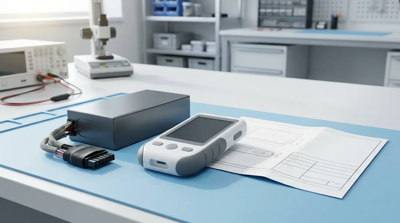
A lithium battery for portable ECG machines is a custom rechargeable battery pack engineered around the device's specific voltage requirements, usable energy and runtime, current profile, mechanical envelope, connector interface, charger compatibility, BMS protection, and applicable safety and transport documentation. Unlike a generic replacement battery, this type of pack is designed from the start as an OEM component, matched to the ECG device's electrical and physical constraints. This guide explains how to specify, design, and validate a compact lithium battery pack for portable ECG equipment.
Portable ECG machines place unusual demands on battery design. They need reliable voltage for sensitive signal acquisition, enough energy for extended monitoring sessions, and enough current for power-hungry operations like display backlighting, wireless transmission, and sometimes printing — all within a compact enclosure that a patient or clinician can carry easily. For engineers and procurement teams evaluating custom medical device battery pack solutions, the key is translating device requirements into a pack specification that a battery manufacturer can engineer, test, and document.
What a Portable ECG Battery Pack Must Do
Before selecting a chemistry or calculating capacity, define what the battery pack must accomplish inside the device. The specification starts with the device, not the cell.
Voltage and power integrity. The pack must maintain voltage within the device's operating range under load. This means matching nominal voltage to the device's input requirement and ensuring the pack can deliver current without excessive voltage sag.
Runtime under real conditions. The battery's capacity in mAh is only meaningful when combined with the device's actual power consumption. Run-time depends on energy in watt-hours (Wh), not raw capacity alone.
Current capability. ECG devices rarely draw a steady current. There is baseline monitoring current, plus higher transient loads from display backlighting, wireless transmission, or data processing. Both continuous and peak current must be specified.
Mechanical fit. The pack must fit inside the device's enclosure, meet weight targets, and connect through a defined connector or wiring harness.
Safe charging. The pack must accept the charger's voltage and current profile without exceeding its limits.
Protection and monitoring. A protection circuit or battery management system (BMS) must guard against overcharge, over-discharge, overcurrent, short circuit, and temperature extremes.
Environmental tolerance. The pack must operate within the temperature range the device will encounter during clinical use, transport, and storage.
Documentation. For medical and transport compliance, the pack needs datasheets, safety data, and test summaries that prove it meets the required standards.
A structured requirements checklist prevents undersizing and avoids mismatches that surface only during prototyping.
| Specification Area | What to Define |
|---|---|
| Electrical | Nominal voltage, charge voltage, capacity, continuous current, peak current |
| Runtime | Device average power, required hours of operation, reserve margin |
| Mechanical | Maximum dimensions, weight limit, connector type, cable length |
| Thermal | Operating temperature range, storage range, charging range |
| Charging | Charger output voltage and current, charging time target |
| Protection | Required BMS functions, balancing, fuel gauge, communication |
| Documentation | Datasheet, SDS/MSDS, UN38.3 test summary, safety test reports |
Li-ion vs LiPo vs LiFePO4: Choosing the Right Chemistry for a Compact ECG Pack
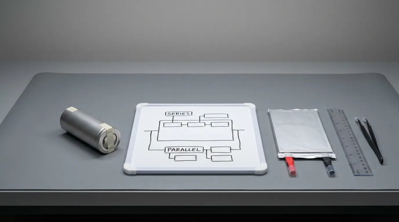
The chemistry choice affects voltage, energy density, cycle life, temperature behavior, safety profile, and physical size. There is no universal best chemistry for every ECG device — the right choice depends on your specific constraints.
Lithium-Ion (Li-ion)
Li-ion cells offer high energy density and a mature supply chain. Cylindrical cells like 18650 or 21700 are mechanically robust and widely available, while prismatic and pouch formats allow design flexibility. For portable ECG machines, Li-ion packs provide a good balance of runtime and weight.
| Attribute | Typical Characteristic |
|---|---|
| Nominal voltage | 3.6–3.7 V per cell |
| Energy density | High |
| Cycle life | Good with proper BMS and charging |
| Form factors | Cylindrical, prismatic, pouch |
| Best for | Compact devices needing high energy in small volume |
Lithium-Polymer (LiPo)
LiPo cells use a polymer electrolyte and are typically packaged in soft pouches. This format allows thinner and more irregular shapes than cylindrical cells, which can be a significant advantage when the ECG device has unusual internal geometry. LiPo packs also achieve good packing efficiency because the cells can fill available space more completely.
| Attribute | Typical Characteristic |
|---|---|
| Nominal voltage | 3.7 V per cell |
| Energy density | High, comparable to Li-ion |
| Form factors | Pouch, thin, flexible, custom shapes |
| Consideration | Requires compression and swelling management in enclosure |
| Best for | Thin devices, irregular cavities, space-constrained designs |
However, LiPo cells can swell slightly over charge/discharge cycles. The enclosure must accommodate this without crushing the cells or stressing the BMS.
Lithium Iron Phosphate (LiFePO4)
LiFePO4 offers excellent cycle life and a stable safety profile, but its nominal voltage is lower than other lithium chemistries — around 3.2 V per cell. This means more cells in series may be required to reach the same pack voltage, which reduces the energy density advantage and increases pack complexity.
| Attribute | Typical Characteristic |
|---|---|
| Nominal voltage | 3.2 V per cell |
| Energy density | Lower than Li-ion/LiPo |
| Cycle life | Excellent |
| Safety profile | Very stable |
| Best for | Applications prioritizing cycle life over compact size |
For a compact portable ECG machine where volume is limited, LiFePO4's lower energy density can be a meaningful disadvantage. It is worth considering only when the device can accommodate the larger pack size and the extended cycle life justifies the trade-off.
Chemistry Selection Table
| Factor | Li-ion | LiPo | LiFePO4 |
|---|---|---|---|
| Nominal cell voltage | 3.6–3.7 V | 3.7 V | 3.2 V |
| Energy density | High | High | Moderate |
| Cycle life | Good | Good | Excellent |
| Shape flexibility | Moderate | High | Moderate |
| Pack volume for same Wh | Compact | Compact | Larger |
| Safety profile | Good with BMS | Good with BMS | Very stable |
| Best suited for | General portable devices | Thin or irregular enclosures | Long-life stationary or larger devices |
When you need the smallest possible pack for a given runtime, Li-ion or LiPo is usually the right direction. Gloflux supports cylindrical, prismatic, and LiPo configurations for lithium ion battery for medical devices, so the form factor can be matched to your enclosure rather than forcing the device to accommodate a standard pack size.
How to Specify Voltage, Capacity, and Runtime for an ECG Battery Pack
The specification process follows a logical sequence from device requirements to pack parameters.
Step 1: Define the Voltage Platform
The device's input voltage determines the nominal pack voltage, which in turn determines the series cell count.
- Determine the device's acceptable input voltage range.
- Select a nominal pack voltage that falls within that range.
- Calculate the series count by dividing the nominal pack voltage by the cell's nominal voltage.
For example, a device expecting roughly 7.4 V nominal input would typically use a 2S configuration (two cells in series) with 3.7 V Li-ion or LiPo cells. A 3S configuration produces approximately 11.1 V nominal.
The maximum charge voltage is also important. A 2S Li-ion pack charges to about 8.4 V, not 7.4 V. The device's charging circuit and the pack's BMS must both tolerate that voltage during charging.
Step 2: Calculate the Energy Requirement
Runtime is determined by energy, not capacity alone. The correct approach:
- Measure the device's average power consumption in watts during typical operation.
- Multiply by the required runtime in hours to get the required energy in watt-hours (Wh).
- Add a safety margin for battery aging, temperature effects, and unexpected peak loads.
For example, if the ECG device consumes an average of 5 W and must run for 8 hours, the required energy is 40 Wh. To maintain that runtime at end of life, a margin of 15–20% is common, placing the target around 46–48 Wh.
Step 3: Convert Energy to Capacity
Capacity in mAh or Ah is derived from energy and voltage:
Capacity (Ah) = Energy (Wh) ÷ Nominal pack voltage (V)
Using the example above, a 48 Wh pack at 7.4 V nominal would need approximately 6.5 Ah of capacity. The same energy at 11.1 V would require only about 4.3 Ah. This is why comparing capacity in mAh across packs of different voltages is misleading — always compare energy in Wh.
Step 4: Define Current Requirements
Identify both the continuous current during normal operation and the peak current during transient events such as system boot, wireless transmission, or display activation. These values determine:
- The C-rate the cells must support.
- The BMS current ratings.
- The connector and wiring gauge.
For example, if the device normally draws 1 A but spikes to 3 A during transmission, the pack must be rated for both conditions. Cells rated only for continuous 1 A discharge may experience excessive voltage sag during the 3 A spike.
Step 5: Determine the S/P Configuration
The series count (S) sets voltage, while the parallel count (P) adds capacity and current capability. A 2S2P configuration, for example, uses two cells in series and two parallel groups, producing the nominal voltage of a 2S pack with roughly double the capacity of a single 2S string.
The S/P configuration affects physical pack size. More parallel cells mean more volume. The design must balance runtime, current capability, and the available space inside the device enclosure.
Understanding C-Rate and Why It Matters for ECG Devices
C-rate expresses the discharge current relative to the cell's capacity. A 1C rate means the current equals the capacity number — for a 3,000 mAh cell, 1C is 3 A. A 0.5C rate would be 1.5 A, and a 2C rate would be 6 A.
C-rate is critical because it determines whether the cell can deliver the current the device demands without excessive voltage drop.
| Load Scenario | Typical Demand | Why It Matters |
|---|---|---|
| Continuous monitoring | Low current near 0.5–1C depending on pack capacity | Normal operation |
| Device boot-up | Brief moderate current | Must not trigger BMS overcurrent protection |
| Wireless transmission | Short high-current pulses | Can cause voltage sag if cell C-rate is insufficient |
| Display backlight at maximum | Moderate sustained current | Adds to baseline load |
| Printing (if supported) | High sustained current | Requires cells rated for continuous high-rate discharge |
Voltage sag occurs when the cell's internal resistance causes the terminal voltage to drop under load. If the sag is severe enough, the device may brown out or the BMS may trigger undervoltage protection even though the cell still holds charge. Specifying the correct C-rate for both continuous and peak loads prevents this failure mode.
BMS, Protection, and Charger Compatibility for Rechargeable Medical Packs
A battery pack for medical equipment needs more than raw cells. The protection electronics are what make the pack safe, reliable, and predictable over its service life.
PCM vs BMS: What's the Difference?
A protection circuit module (PCM) provides basic safety functions. It monitors the pack and interrupts current flow when it detects an abnormal condition. Typical PCM functions include:
- Overcharge protection (stops charging above the voltage limit)
- Over-discharge protection (stops discharging below the minimum voltage)
- Overcurrent protection (interrupts excessive current)
- Short-circuit protection
- Temperature protection (in some designs)
A battery management system (BMS) provides the same protection functions but adds active management and monitoring. A smart BMS can include:
- Cell balancing to maintain voltage consistency across series cells
- Fuel gauging to estimate state of charge and remaining runtime
- State-of-health monitoring
- Data logging
- Communication protocols (SMBus, I2C, UART, CAN, or Bluetooth) for integration with the device's firmware
For a medical device that reports remaining battery time to the clinician, a smart BMS with fuel gauging is typically the right choice. For a simpler device where the ECG machine only needs to know when the battery is low, a well-configured PCM may be sufficient.
Essential Protections
| Protection | Function |
|---|---|
| Overcharge | Prevents cell voltage from exceeding the maximum charge voltage |
| Over-discharge | Prevents cell voltage from dropping below the minimum safe level |
| Overcurrent | Limits current to a safe maximum, protecting cells and wiring |
| Short-circuit | Interrupts current on short-circuit events |
| Temperature | Halts charge or discharge outside the safe temperature window |
Balancing in Series Packs
When cells are connected in series, small differences in capacity or internal resistance can cause voltage divergence over time. If one cell reaches full charge before the others, the charger must stop before that cell is overcharged — which may leave the other cells undercharged. Balancing equalizes the cell voltages, improving pack consistency and usable cycle life.
Charger Compatibility
The charger must match the pack's chemistry, series count, and charge limits. The charging profile for lithium cells is typically constant current followed by constant voltage (CC/CV). The pack's charge voltage is the maximum voltage of the full series string, and the charge current must not exceed the pack's rated charge current.
A mismatch between charger and pack is one of the most common causes of premature pack failure. The OEM should either specify the charger or provide the battery manufacturer with the charger's output characteristics so the pack's protection thresholds can be coordinated.
Communication Protocols
If the device needs to read state of charge, remaining runtime, or battery health, the BMS must support the device's communication interface. Common protocols include SMBus and I2C, which are widely used in smart battery packs. Specify the protocol clearly in the requirements — it affects BMS selection and firmware integration.
Gloflux designs custom medical device rechargeable battery pack solutions with BMS configurations matched to the application's protection and monitoring needs.
Compact Mechanical Integration: Connector, Enclosure, and Thermal Path
The mechanical design is just as important as the electrical specification. A pack that fits poorly, moves inside the enclosure, or overheats can cause failures that have nothing to do with cell quality.
Mechanical Requirements Checklist
| Item | Key Considerations |
|---|---|
| Envelope dimensions | Must fit within the device's allocated battery cavity |
| Weight | Must meet the device's total weight target |
| Connector type | Must match the device's mating connector, pinout, and current rating |
| Wire gauge | Must be sized for the peak current without excessive voltage drop |
| Cable length | Must reach the device connection point without strain |
| Enclosure material | Must provide insulation, mechanical protection, and fire resistance |
| Mounting | Must secure the pack against vibration and shock |
| Thermal path | Must allow heat from cells and BMS to dissipate |
| Pouch-cell compression | Must accommodate LiPo swelling without excessive pressure |
Connector and Wiring
The connector must handle the peak current continuously without overheating. A connector rated for continuous current above the device's maximum draw is essential, and locking or keyed connectors prevent accidental disconnection or reversed polarity.
The wiring gauge must match the current. Undersized wires add resistance, causing voltage drop and heat generation under load.
Enclosure and Insulation
The enclosure does more than hold the cells. It provides:
- Electrical insulation between the cells and the device's internal components.
- Mechanical protection during handling and drops.
- A degree of environmental protection where needed.
If the device requires resistance to moisture or dust, an IP rating may be specified. An IP-rated enclosure is different from a general statement that a pack is "waterproof" — the rating must be defined and tested against a recognized standard with a specific threshold.
Thermal Considerations
Lithium cells generate heat during discharge, and charging generates heat as well. In a compact device with limited airflow, the heat must have a path out of the pack and the device. The BMS also produces heat, particularly during balancing or high-current events.
The thermal design must keep cell temperatures within the manufacturer's specified range during both charging and discharging. If the device will be used in a warm clinical environment, the thermal margin narrows and must be verified.
Pouch-Cell Compression
LiPo pouch cells can swell slightly during cycling. The enclosure must allow for this expansion without crushing the cells and without allowing them to move excessively. A small amount of compression is acceptable and often desirable, but the design must be validated over the expected cycle life.
From Prototype to Production: Validation, Testing, and Documentation
A custom lithium battery pack does not go straight from specification to mass production. It moves through a development and validation process that confirms the design meets the requirements — and produces the documentation needed for transport, safety, and device integration.
Development Workflow
- Requirements review — The OEM and battery manufacturer align on voltage, capacity, current, mechanical, charging, and documentation requirements.
- Cell selection — Cells are chosen based on capacity, C-rate, temperature range, dimensions, and supply-chain reliability.
- Pack architecture design — S/P configuration, BMS/PCM, connector, wiring, and enclosure are designed.
- Prototype build — A small number of packs are built for design verification.
- Design validation — The prototypes are tested against the requirements: voltage, capacity, current, temperature, cycle life, and mechanical fit.
- Sample approval — The OEM approves the samples against an agreed specification.
- Pilot production — A small production run verifies manufacturability and consistency.
- Mass production — Full production begins, with quality control and traceability in place.
Testing and Validation
| Test Type | Purpose |
|---|---|
| Capacity test | Confirms the pack delivers the rated capacity under defined conditions |
| Cycle life test | Validates performance over the expected service life under specific test conditions |
| Internal resistance measurement | Confirms cells and pack connections meet targets |
| Vibration and shock | Verifies the pack survives transport and device handling |
| Overcharge/over-discharge protection | Confirms the BMS/PCM protects the pack |
| Short-circuit protection | Confirms the protection circuit interrupts fault currents |
| Temperature testing | Validates performance across the specified operating and storage range |
| Cell matching | Ensures cells in series strings are closely matched in capacity and internal resistance |
Documentation Requirements
| Document | Purpose | Responsibility |
|---|---|---|
| Datasheet/TDS | Defines the pack specification, performance, and test conditions | Battery manufacturer |
| SDS/MSDS | Provides safety and handling information | Battery manufacturer |
| UN38.3 test summary | Supports transport of lithium cells and batteries | Battery manufacturer |
| IEC 62133-2 test report | Demonstrates compliance with portable sealed lithium battery safety standard, where applicable | Battery manufacturer |
| Complete-device certification (e.g., IEC 60601-1) | Covers the full medical electrical system | Device OEM |
UN38.3 transport testing is not the same as IEC/UL product safety testing. UN38.3 is a transport test regime required for shipping lithium cells and batteries. It does not certify the battery for medical use, and it is not a substitute for IEC 62133-2 or UL product safety testing.
Similarly, a battery used in medical equipment is not automatically a certified complete medical device. The battery must meet its own component-level safety standards, but the complete ECG machine's compliance with system-level standards like IEC 60601-1 remains the device OEM's responsibility.
IATA requires that lithium cell and battery types have passed the applicable UN Manual of Tests and Criteria Section 38.3 tests before they are transported by air. Transport Canada similarly identifies UN38.3 testing as the mechanism to mitigate hazards during lithium battery transport. The UN38.3 test summary must be provided by the battery manufacturer for each cell and battery type shipped.
Traceability and Change Control
For medical devices, traceability is essential. The battery manufacturer should maintain batch records linking each pack to its cells, BMS components, and production lot. If a component is changed, a formal change-control process should notify the OEM before the change affects production.
This is particularly important because the cells inside the pack may be sourced from different cell manufacturers or suppliers over the product's life. Substituting a different cell that appears equivalent on paper can change internal resistance, temperature behavior, cycle life, or safety characteristics. Change control prevents unauthorized substitutions from reaching production.
What to Send in an RFQ for a Custom ECG Battery Pack

The quality of the battery manufacturer's response depends on the quality of your requirements. A complete request for quotation (RFQ) gives the manufacturer the information needed to propose the right cells, architecture, BMS, and enclosure.
RFQ Checklist
Electrical requirements
- Nominal voltage
- Minimum and maximum device input voltage
- Required capacity in mAh or Ah
- Required energy in Wh
- Continuous current
- Peak current and its duration
- Acceptable voltage sag under peak load
Runtime requirements
- Average device power in watts
- Required runtime in hours
- Reserve margin target
Mechanical requirements
- Maximum dimensions (L × W × H)
- Weight limit
- Connector type and pinout
- Cable length and connector orientation
- Mounting method, if applicable
Charging requirements
- Charger output voltage and current
- Target charge time
- Charging temperature range
Environmental requirements
- Operating temperature range
- Storage temperature range
- Humidity or IP requirements, if any
- Vibration or shock levels, if known
Protection and BMS requirements
- Required protections (overcharge, overdischarge, overcurrent, short circuit, temperature)
- Cell balancing (required for multi-series packs)
- Fuel gauge and state-of-charge reporting
- Communication protocol (SMBus, I2C, UART, CAN, Bluetooth), if needed
Documentation requirements
- Datasheet
- SDS/MSDS
- UN38.3 test summary
- IEC/UL test reports, if applicable
- Traceability and batch records
- Change-control notification process
Commercial requirements
- Target quantity (annual or per order)
- Prototype quantity and timeline
- Production timeline
- Quality agreement requirements
A universal battery that fits every ECG machine does not exist. Each portable ECG device has its own voltage platform, load profile, mechanical envelope, and charging arrangement. The pack must be designed around the specific device. Suppliers that claim a single replacement battery works across many models should be asked to prove compatibility with your specific device model and revision.
Moving from Specification to Custom Pack Design
By this point, the path is clear: define the device's electrical and mechanical requirements, select the chemistry and cell format that fits the enclosure, configure the S/P architecture for the right voltage and capacity, specify the BMS and charger interface, validate the mechanical and thermal design, and ensure the documentation supports transport, safety, and device-level integration.
The requirements-to-RFQ workflow prevents the most common failure modes: undersized capacity, insufficient current rating, voltage sag under peak load, BMS nuisance trips, charging incompatibility, connector mismatch, and documentation gaps.
When the requirements are clear, a custom battery manufacturer can engineer a pack that fits the device — not the other way around. Gloflux designs custom lithium battery packs for medical devices including portable diagnostic equipment, with customization based on device size, voltage, discharge rate, and operating conditions. Applications like Lithium battery for portable blood analyzers follow a similar engineering pattern: compact enclosure, defined load profile, and strict documentation needs.
If you are specifying a battery for a portable ECG machine, the next step is to translate your device's requirements into a project brief. Share the voltage platform, runtime target, current profile, mechanical envelope, and required documentation with a battery manufacturer that can evaluate the full design — not just supply a cell.
Talk to the Manufacturer
Resources & Insights

High Capacity Lithium Battery for Wearables: High-Voltage LiPo Cell Design
2026-10-19

Cylindrical Battery Packs for Laptops: 2S vs 3S vs 4S Battery Design
2026-10-19

Stage Lighting Battery Pack: Prevent Voltage Drop & LED Flicker
2026-10-19

Best Rechargeable Batteries for Smart Devices: Performance, Safety, and Selection Guide
2026-10-19


