


 Home /
 Custom Battery Pack for LoRaWAN Sensors: Low-Power OEM Design


Table of Contents
- What a LoRaWAN Sensor Battery Pack Must Do
- Translating the Load Profile into a Battery Pack Specification
- Estimating Runtime for a LoRaWAN Sensor Battery
- Choosing the Right Chemistry and Pack Architecture
- Protection and Battery Management: PCM vs BMS
- Physical Integration, Temperature, and the Environment
- Charging Your LoRaWAN Sensor Battery Pack
- Validation, Testing, and Documentation
- What to Send Your Battery Manufacturer: An RFQ Checklist
- Why Work with a Custom Battery Manufacturer for LoRaWAN Sensors
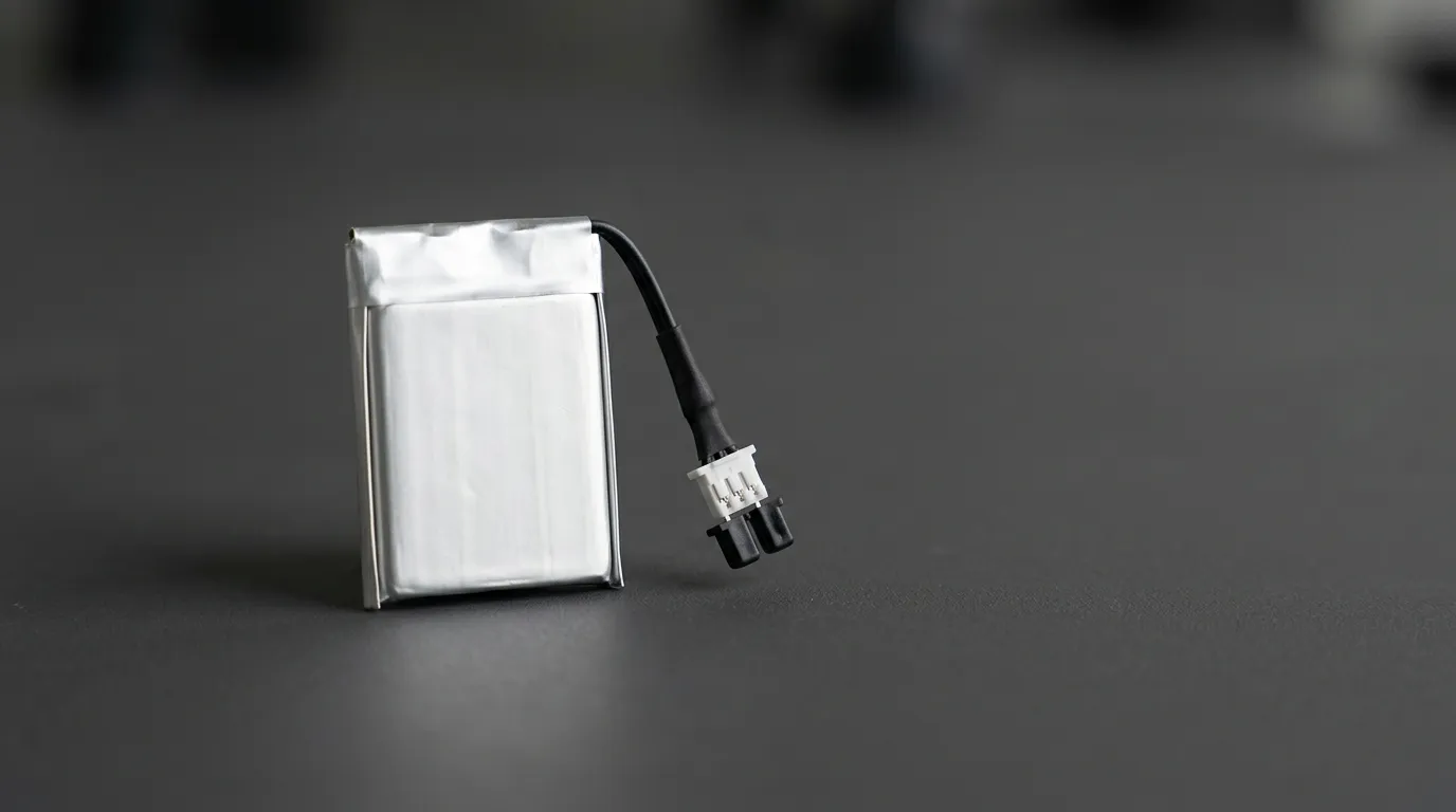
A custom battery pack for LoRaWAN sensors is a battery system engineered around the sensor's complete duty cycle—including sleep current, measurement events, radio transmit and receive bursts, retries, and environmental conditions—rather than selected by capacity alone. Getting the design right requires translating the sensor's load profile into a complete specification covering voltage, energy, pulse current capability, chemistry, protection, mechanical integration, and documentation.
LoRaWAN sensors occupy a distinct position within the broader category of custom battery for IoT hardware. Unlike always-on connected devices, LoRaWAN sensors spend most of their lives in deep sleep, waking briefly to take measurements and transmit small data packets. That duty cycle creates a unique set of battery demands that off-the-shelf cells often fail to meet.
This guide explains how to specify, design, and source a custom battery pack for a LoRaWAN sensor—and what to send your battery manufacturer when you request a quote.
What a LoRaWAN Sensor Battery Pack Must Do
A LoRaWAN sensor's energy consumption is defined by how it moves through different power states over time. The battery must support each state with the right voltage, current capability, and total energy—without being oversized for the enclosure.
Several factors determine how quickly a LoRaWAN sensor drains its battery:
- Sleep current: Most LoRaWAN sensors spend the majority of their time in a low-power sleep mode. Sleep current is measured in microamps (µA) or milliamps (mA) and is often the largest contributor to long-term energy use.
- Measurement or sensing current: Reading a soil moisture probe, temperature sensor, or other transducer draws current for a short period. The frequency and duration of readings affect total energy.
- Uplink interval: How often the sensor transmits is the single most important firmware-controlled variable. More frequent uplinks consume more energy.
- Payload size: Larger data packets take longer to transmit. Longer transmission time means higher energy consumption per message.
- Spreading factor: LoRaWAN uses spreading factors (SF7 through SF12) to balance range and data rate. Higher spreading factors increase transmission time. Research shows that higher spreading factors reduce throughput and increase the energy consumed per transmitted bit because the radio is active longer. This relationship is documented in peer-reviewed literature on LoRaWAN energy consumption.
- Transmit power: The radio's output power setting directly affects the current drawn during transmission. Higher output power increases pulse current demand.
- Receive windows: After each uplink, a Class A device opens one or two short receive windows to listen for downlink messages. These brief receive periods add to energy consumption.
- Retries and downlinks: Poor coverage, network congestion, or frequent downlink messages can increase the number of transmit and receive events, adding hidden energy use.
For a battery engineer, the takeaway is simple: the load profile is a combination of very low average current and short, high-current radio bursts. The battery must handle both without excessive voltage sag and without being physically larger than the sensor enclosure allows.
Translating the Load Profile into a Battery Pack Specification
Once the load profile is understood, the next step is converting it into a formal battery pack specification. This requires defining several electrical parameters precisely.
Nominal Voltage and Maximum Charge Voltage
The battery's nominal voltage must fall within the sensor's input voltage range. For example, a 3.7 V Li-ion pack provides a nominal voltage that is compatible with many 3.3 V sensor systems through a voltage regulator.
The maximum charge voltage is the highest voltage the pack may reach during charging. For a single-cell Li-ion pack, that is typically 4.2 V. Do not confuse nominal voltage with maximum charge voltage—they are different values with different purposes.
Capacity, Energy, and Runtime
Battery capacity is measured in milliamp-hours (mAh) or amp-hours (Ah). Capacity indicates how much charge the battery can deliver under specified conditions.
Battery energy is measured in watt-hours (Wh) and is calculated as nominal voltage × capacity. A 3.7 V, 2,000 mAh pack contains approximately 7.4 Wh of energy.
Runtime cannot be determined from capacity alone. Two packs with the same mAh rating can deliver very different field life if their voltage platforms differ, their internal resistance is different, or they are used at different temperatures. Energy (Wh) is a more reliable unit for comparing candidate designs, but even Wh must be evaluated against the actual load profile, self-discharge, and temperature derating.
Continuous Current vs. Peak Pulse Current
A LoRaWAN sensor's average current may be measured in microamps, but its radio can draw hundreds of milliamps during a transmit burst. These two values place very different demands on the battery.
- Continuous current is the current the battery must sustain over an extended period.
- Peak or pulse current is the short-duration current the battery must support during radio transmission, typically for a second or less.
A battery with high capacity but poor pulse current capability can experience severe voltage sag during transmission, potentially causing the sensor to reset. The pulse current requirement is often more important than the capacity figure when selecting cells for a LoRaWAN application.
Series and Parallel Configurations
Battery packs are built by combining cells in series and parallel:
- Series (S) increases voltage. Two 3.7 V cells in series produce a 7.4 V pack.
- Parallel (P) increases capacity and available current. Two 2,000 mAh cells in parallel produce a 4,000 mAh pack at the same voltage.
A "2S1P" pack means two cells in series and one in parallel. The configuration must match the device's voltage requirement, energy target, and current demand.
Voltage Sag and Internal Resistance
Every cell has internal resistance. When current flows, that resistance causes the pack voltage to drop. The drop is called voltage sag. During a radio transmit burst, even a short pulse of high current can cause the voltage to dip below the sensor's minimum operating voltage, causing a brownout or reset.
Low internal resistance is therefore essential for LoRaWAN applications, especially at low temperatures where resistance increases. When selecting cells, the OEM should consider the cell's internal resistance, not just its capacity.
Specification Table for a LoRaWAN Battery Pack
A complete battery pack specification should include at least the following fields:
| Specification | What to Define |
|---|---|
| Nominal voltage | Voltage delivered under normal load |
| Maximum charge voltage | Highest voltage allowed during charging |
| Minimum operating voltage | Cutoff or device minimum voltage |
| Capacity | mAh or Ah under specified discharge conditions |
| Energy | Wh (nominal voltage × capacity) |
| Continuous current | Sustained current capability |
| Peak/pulse current | Short-duration current and its allowed duration |
| Internal resistance | Cell or pack resistance value |
| Operating temperature | Separate charge and discharge ranges |
| Storage temperature | Recommended storage range |
| Dimensions | Length, width, height |
| Weight | Pack weight |
| Connector | Type, pinout, locking mechanism |
| Wiring | Wire gauge, length, termination |
| Charging method | CC/CV, charge current, charge voltage |
| Protection | PCM or BMS functions |
| Certifications/documentation | Datasheet, SDS, UN38.3, test reports |
Estimating Runtime for a LoRaWAN Sensor Battery
Runtime estimation is not an exact science, but a simple method gives a useful first approximation.
Step 1: Define the duty cycle.
For each state (sleep, measurement, transmit, receive), estimate the current draw and the duration per cycle.
Step 2: Calculate average current.
Multiply each state's current by its duration, sum the results, and divide by the total cycle time.
Step 3: Convert to energy.
Multiply the average current by the nominal voltage and the target runtime to estimate the required energy in Wh.
Step 4: Add a safety margin.
Account for self-discharge, temperature derating, cell aging, and the fact that real-world radio performance varies. A 20–30% margin is common practice, but the exact margin depends on the application's reliability requirements.
This method is a planning tool, not a guarantee. Actual runtime depends heavily on firmware behavior, network conditions, temperature, and cell selection. No responsible manufacturer should promise a specific number of years of battery life without a complete load profile and environmental specification.
Choosing the Right Chemistry and Pack Architecture
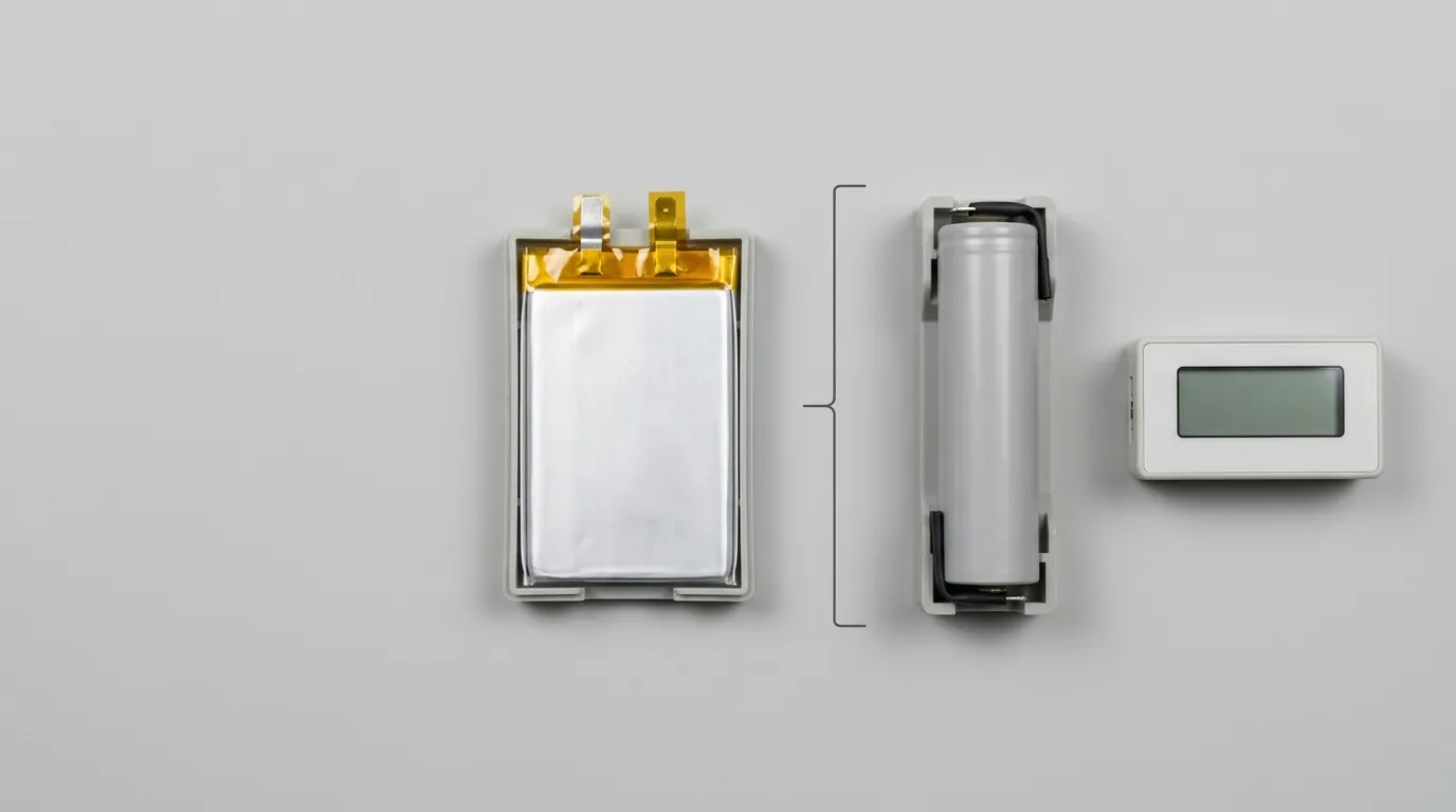
The chemistry choice for a LoRaWAN sensor battery pack depends on voltage, energy, charging access, temperature, and maintenance requirements.
| Chemistry | Typical Nominal Voltage | Rechargeable | Key Characteristics | Typical Use |
|---|---|---|---|---|
| Li-ion (lithium-ion) | 3.7 V | Yes | High energy density, good cycle life, requires protection circuitry | Rechargeable sensor packs |
| LiPo (lithium-polymer) | 3.7 V | Yes | Thin, flexible form factors; compact designs; requires protection | Space-constrained sensors |
| LiFePO4 (lithium iron phosphate) | 3.2 V | Yes | Longer cycle life, stable safety profile, lower voltage | Applications needing long cycle life |
| Primary lithium (Li-SOCl₂) | 3.6 V | No | Very long shelf life, low self-discharge, non-rechargeable | Battery-life-critical, maintenance-free deployments |
Li-ion offers a good balance of energy density and rechargeability. A single-cell 3.7 V Li-ion pack is a common choice for LoRaWAN sensors that can be recharged or replaced periodically.
LiPo packs are available in thin, custom shapes that fit tightly inside sensor enclosures. Because they are pouch cells rather than rigid cylinders, they are often the right choice when the enclosure design is space-constrained. A lipo battery for wireless monitoring systems is often the practical answer for compact, low-profile sensor designs.
LiFePO4 operates at a lower nominal voltage (3.2 V) and offers a longer cycle life with a stable safety profile. It is a strong choice when the device is designed for that voltage platform and the deployment requires many charge cycles.
Primary lithium cells such as Li-SOCl₂ are widely used in LoRaWAN sensors where long field life and maintenance-free operation matter more than rechargeability. For example, the Dragino PS-LB-NA LoRaWAN analog sensor uses an 8,500 mAh Li-SOCl₂ battery and specifies an operating temperature range for the complete device. Primary lithium is an excellent choice for many remote sensors, but the pulse current capability of primary cells must be checked carefully against the radio's transmit current demands.
There is no universal "best" chemistry. The right choice depends on the device's voltage range, energy target, charging access, temperature requirements, and physical constraints. A rechargeable battery for iot sensors makes sense when the sensor is accessible and can be recharged. A primary cell or a sealed pack may be better when the sensor is installed once and expected to operate for years.
Protection and Battery Management: PCM vs BMS
Every lithium-based battery pack needs some form of protection. The question is whether basic protection is sufficient or a full battery management system (BMS) is required.
PCM (Protection Circuit Module) provides essential safety functions:
- Overcharge protection
- Over-discharge protection
- Overcurrent protection
- Short-circuit protection
A PCM is typically sufficient for a single-cell pack with no balancing or communication requirements. Many LoRaWAN sensors with a single 3.7 V Li-ion or LiPo cell need no more than a PCM.
BMS (Battery Management System) adds more advanced functions:
- Cell balancing (for multi-cell series packs)
- Fuel gauging (state of charge estimation)
- Temperature monitoring
- Communication protocols (SMBus, I2C, UART, CAN, RS485, or Bluetooth)
A BMS is appropriate when the pack has multiple cells in series, when the device needs accurate remaining-runtime information, or when the pack must communicate with the host system. For a simple single-cell LoRaWAN sensor, a BMS may be more capability than the application requires.
The choice between PCM and BMS is not about which is "better"—it is about which is appropriate for the pack architecture and the sensor's monitoring needs.
Physical Integration, Temperature, and the Environment
A custom battery pack must fit the sensor's physical envelope and survive its operating environment.
Connectors and Wiring
The connector and wiring are part of the battery specification, not an afterthought. The connector must:
- Match the device's mating connector
- Support the required continuous and pulse current without overheating
- Provide secure, polarity-correct connections
- Withstand vibration if the sensor is mobile or mounted in a harsh environment
Wire gauge must be sized for the current. A thin wire may be fine for a sensor that draws microamps, but it may drop excessive voltage during a radio transmit burst.
Enclosure and Ingress Protection
The pack enclosure affects dimensions, weight, heat dissipation, and ingress protection. An IP rating (such as IP65 or IP67) indicates a specific level of protection against dust and water. "Waterproof" is not a specification—an IP rating is. If the sensor will be mounted outdoors, in a well, underground, or in a cold-chain environment, the enclosure and connector must be specified for that exposure.
Temperature Limits
Temperature profoundly affects battery performance.
- Charge temperature: Acceptable temperature range for charging. Charging lithium batteries at very low or very high temperatures is unsafe or may be prohibited by the protection circuit.
- Discharge temperature: Acceptable range for discharging. Cold temperatures increase internal resistance and reduce available capacity.
- Storage temperature: Recommended temperature for long-term storage without significant degradation.
A LoRaWAN sensor deployed outside in winter may experience temperatures below -20 °C. At those temperatures, a battery's pulse current capability drops significantly. The cell selection must account for the actual minimum discharge temperature, not just the average.
For cold-chain monitoring applications, low-temperature performance is a primary design requirement. A Custom battery for cold chain trackers addresses the specific power considerations for temperature-sensitive tracking deployments.
Charging Your LoRaWAN Sensor Battery Pack
If the sensor uses a rechargeable pack, the charging system must match the battery chemistry and series configuration.
Lithium-ion and LiPo batteries are typically charged using a CC/CV (constant current / constant voltage) profile:
- Constant current is applied until the pack reaches its maximum charge voltage.
- Constant voltage is held while the charging current tapers down.
- Charging terminates when the current drops below a threshold or a timer expires.
The charger's output voltage and current must match the pack's specified limits. A charger designed for a 2S Li-ion pack must not be used on a 1S pack. Charging at too high a current or voltage is unsafe and can damage the pack or the protection circuit.
The charging method must also be specified in the battery requirements: USB-C, barrel jack, wireless charging, or an integrated charging circuit on the sensor's PCB. The battery design must integrate with the chosen charging architecture.
Validation, Testing, and Documentation
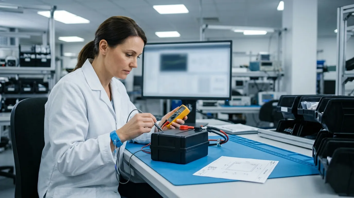
A custom battery pack should not go into production without validation. The OEM and the battery manufacturer should agree on the testing and documentation requirements before the first prototype is built.
Prototype Testing
A functional prototype should be tested for:
- Electrical performance (capacity, voltage, current, BMS behavior)
- Mechanical fit (dimensions, connector, wiring)
- Temperature performance (charge, discharge, storage)
- Environmental resistance (if the application requires it)
Sample approval is a formal step. The OEM should not proceed to mass production until prototypes have been tested in the actual device and approved.
Transport and Safety Documentation
Lithium batteries are regulated for transport. A custom pack will typically require:
- UN38.3 test summary — evidence that the battery design has passed the United Nations transport tests for lithium batteries. UN38.3 is a transport testing requirement, not a product-safety certification.
- SDS (Safety Data Sheet) — documentation for safe handling and emergency response.
- Product safety reports — IEC, UL, or CB test reports, where applicable. These apply to a defined model and construction, and they are not the same as a UN38.3 test summary.
The OEM should ask the battery manufacturer exactly which documents will be provided for the specific pack design.
Traceability and Change Control
Traceability matters for quality and warranty. The manufacturer should be able to trace cells to their original lots and identify when a pack was built.
Change control is equally important. If the manufacturer substitutes a different cell or changes the BMS, the pack's performance can change. The OEM should require written notification before any cell, component, or process change is made.
What to Send Your Battery Manufacturer: An RFQ Checklist
A well-prepared request for quotation (RFQ) saves time and produces a more accurate quote. The more complete the specification, the less room there is for misunderstanding.
| Item | What to Provide |
|---|---|
| Load profile | Sleep current, measurement current, transmit current, receive current, durations, and cycle times |
| Target battery life | Desired runtime or service interval |
| Voltage requirements | Nominal voltage, minimum operating voltage, maximum charge voltage |
| Capacity/energy target | mAh or Wh target, if known |
| Physical dimensions | Available space for the battery pack |
| Connector and wiring | Connector type, pinout, wire gauge, wire length |
| Operating temperature | Charge, discharge, and storage ranges |
| Charging method | Charger type, charging voltage, charging current |
| Environmental requirements | IP rating, vibration, drop, humidity |
| Documentation required | Datasheet, SDS, UN38.3, test reports, declarations |
| Commercial requirements | Estimated annual quantity, target timeline, target cost |
A complete specification also includes the PCB layout constraint, if the pack connects directly to the board, and any regulatory or market access requirements for the finished device.
LoRaWAN sensors are increasingly used in connected-building and smart-home environments, where a Custom lithium ion battery for smart home devices may follow a similar design approach adapted to indoor conditions and regulatory requirements.
Gloflux's engineering team can assess a project brief and recommend a battery architecture based on the sensor's actual load profile and mechanical constraints. The customized lithium battery solutions page describes the company's custom battery development process, from needs assessment through prototype testing and mass production.
Why Work with a Custom Battery Manufacturer for LoRaWAN Sensors
Standard off-the-shelf batteries rarely match the exact combination of voltage, pulse current, dimensions, connector, and temperature range that a LoRaWAN sensor requires. A custom pack can be engineered around the sensor's specific duty cycle, enclosure, and environmental conditions.
Gloflux's custom battery development process covers needs assessment, cell sourcing, engineering design, prototype testing, mass production, and after-sales support. The company supports custom size, capacity, and voltage configurations, allowing the battery to be shaped to the sensor rather than forcing the sensor to accommodate a standard battery.
For an OEM, the benefit is a battery pack that fits the enclosure, supports the radio's pulse current, operates in the deployment environment, and arrives with the documentation required for transport and field use.
Send Gloflux your load profile, mechanical constraints, and target battery life. The engineering team can assess feasibility and propose a custom battery pack design for your LoRaWAN sensor.
Talk to the Manufacturer
Resources & Insights

High Capacity Lithium Battery for Wearables: High-Voltage LiPo Cell Design
2026-10-19

Cylindrical Battery Packs for Laptops: 2S vs 3S vs 4S Battery Design
2026-10-19

Stage Lighting Battery Pack: Prevent Voltage Drop & LED Flicker
2026-10-19

Best Rechargeable Batteries for Smart Devices: Performance, Safety, and Selection Guide
2026-10-19


