


 Home /
 Custom Battery for TWS Earbud Charging Cases: Compact OEM Design


Table of Contents
- Battery Basics for a Charging Case
- How to Specify a Custom TWS Charging-Case Battery
- Electrical and Charging Compatibility
- Form-Factor and Enclosure Considerations
- Protection and BMS Choices
- Capacity and Runtime Planning
- Prototype and Validation Workflow
- Documentation and Market Access
- Supplier RFQ and Selection
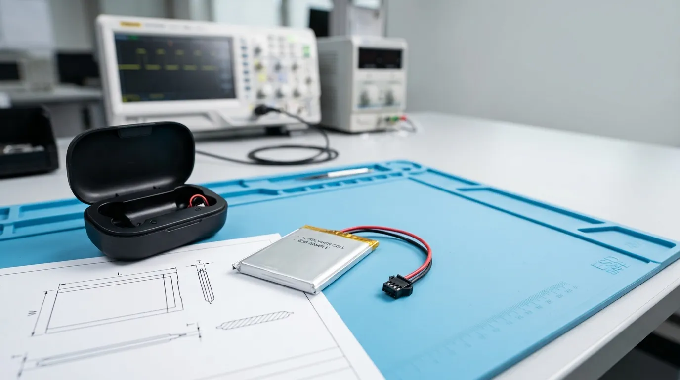
A custom battery for TWS earbud charging cases is a device-specific rechargeable lithium-ion or lithium-polymer pack whose voltage, capacity, dimensions, connector, protection circuitry, and charging behavior must be matched to the case's power-management electronics and the energy required to recharge the earbuds. Unlike a generic replacement cell, a custom battery is engineered as part of the charging case system, with the cell, protection circuit, and mechanical interface specified together for one product design.
This guide explains how OEM engineers and product teams specify, validate, and source a compact battery for a TWS charging case, from the initial requirements checklist through prototype testing and supplier evaluation. For broader guidance on custom batteries across Bluetooth audio devices, see our guide to custom lithium battery for bluetooth speakers (inferred).
Battery Basics for a Charging Case
A TWS charging case battery is not simply a bare cell dropped into an enclosure. It is a small battery pack that typically combines three elements: the lithium cell itself, a protection circuit (PCM), and the mechanical and electrical interface that connects it to the case PCB.
The distinction matters because a bare lithium cell lacks the protection and connection features required for safe integration into a consumer product. A custom battery pack adds:
- Protection circuitry against overcharge, over-discharge, overcurrent, and short-circuit conditions
- A connector or welded wiring that matches the case PCB interface
- Insulation and mechanical retention so the cell stays fixed and protected inside the enclosure
- Labeling or packaging configured for the product's assembly process
The cell chemistry also matters. Most compact charging cases use lithium-ion or lithium-polymer (LiPo) cells, but the two are not interchangeable terms. Lithium-ion describes a chemistry family; lithium-polymer describes a pouch-type construction that uses a polymer electrolyte. In practice, "LiPo pouch" is the form factor most commonly associated with thin, space-constrained devices like TWS charging cases, but the correct choice depends on the mechanical envelope, current requirements, and charging system. For a broader look at pouch cells in wireless audio products, see our guide to lipo battery for bluetooth devices.
Gloflux supplies customized battery solutions for Bluetooth audio devices, including TWS earbuds, with the ability to customize voltage, capacity, dimensions, cell configuration, connector type, wire length, polarity, protection circuit, and packaging for each project.
How to Specify a Custom TWS Charging-Case Battery
The specification process starts with the device, not the battery. Before contacting a supplier, define the mechanical and electrical constraints of the charging case so the battery can be engineered around them.
The Minimum Information Checklist
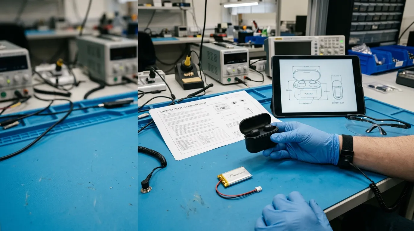
A complete battery specification for a TWS charging case should include:
- Available cavity dimensions — length, width, and maximum thickness of the battery compartment, including tolerance
- Battery mass limit — if the product has a weight target
- Connector type and pitch — or whether welded wiring is preferred
- Polarity orientation — which pad or wire is positive and negative
- Wire exit direction — where the cable leaves the battery relative to the connector
- Charger input specifications — voltage and current available from the case charging circuit
- Load current — the current drawn by the case electronics and during earbud charging
- Earbud battery capacity — so the case battery can be sized for the intended recharge count
- Target recharge count — how many full earbud charges the case should provide
- Operating and storage temperature range — for the intended market and use environment
- Required documentation — datasheet, SDS/MSDS, UN38.3 transport documentation, or product safety reports
The table below summarizes the specification fields a supplier needs to begin an RFQ or sample evaluation.
| Specification Field | What to Define | Why It Matters |
|---|---|---|
| Cavity dimensions | Length × width × max thickness (mm) | Determines cell size and pack envelope |
| Mass limit | Maximum battery weight (g) | Affects handling and product weight targets |
| Nominal voltage | e.g., 3.7V platform | Must match the charging circuit design |
| Charge voltage | Maximum voltage the charger applies | Must match cell chemistry and series count |
| Capacity | Target mAh or Ah | Determines stored charge and recharge count |
| Continuous current | Maximum sustained load (A) | Must exceed the actual case load |
| Peak current | Short-duration transient (A) | Can cause voltage sag or protection trips |
| Connector/wiring | Type, pitch, wire gauge, exit direction | Must match the PCB mechanical interface |
| Polarity | Positive/negative orientation | Reversed polarity can damage the PCB |
| Charger input | Voltage and current into the case | Defines charging time and thermal load |
| Operating temperature | Charge and discharge ranges (°C) | Affects cell selection and performance |
Electrical and Charging Compatibility
The electrical specification of a custom TWS charging-case battery must match the case's power-management electronics. Two distinctions are critical to get right.
Nominal voltage versus maximum charge voltage. A cell with a 3.7V nominal voltage does not charge to 3.7V. The nominal voltage is the average operating voltage during discharge; the maximum charge voltage is the upper limit the charger applies. For many Li-ion/LiPo chemistries, that maximum is around 4.2V per cell, but the exact value depends on the cell chemistry and the manufacturer's specification. If the charging circuit applies a higher voltage than the cell allows, the cell can be overcharged, which risks damage or safety failure. If the voltage is too low, the cell will not reach full charge.
Capacity versus energy. Capacity is measured in milliampere-hours (mAh) or ampere-hours (Ah) and describes the total charge a battery can deliver under defined test conditions. Energy is measured in watt-hours (Wh) and is calculated as nominal voltage × capacity. A 500mAh cell at 3.7V nominal contains approximately 1.85Wh of energy. A cell with the same mAh rating at a different voltage would contain different energy. When comparing batteries, use the same metric — mAh alone is not a complete specification without voltage.
Continuous versus peak current. The continuous current is the sustained load the battery can support within its design limits. The peak current is a short-duration transient that may cause voltage sag or trigger protection circuitry if the threshold is set too low. The case electronics and the earbud charging load determine both values. A battery must be rated for the actual continuous current, not just the average, and the protection circuit must allow the peak current without nuisance tripping.
C-rate describes the current relative to the cell's capacity. A 1C rate for a 500mAh cell is 500mA; a 0.5C rate is 250mA. The required C-rate depends on how quickly the case must charge the earbuds and support its own electronics.
Internal resistance affects voltage sag and heat generation. A cell with higher internal resistance will show a larger voltage drop under load, which can cause the charging circuit to misread the battery state or trigger protection unnecessarily.
Charging-IC compatibility. The case's charging IC defines the charge voltage, charge current, and termination method. A custom battery must be compatible with that IC. If the IC is designed for a 4.2V charge limit, the cell must accept that limit. If the IC uses a specific termination current, the cell's charging behavior must be compatible to avoid undercharging or overcharging. The same compatibility logic applies across portable audio products; for example, a lipo battery for portable speaker must also match its device's charging profile, though the load and enclosure constraints differ from a compact charging case.
Form-Factor and Enclosure Considerations
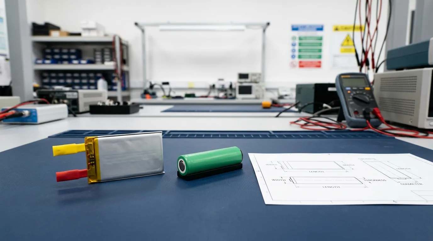
The physical design of the battery is as important as its electrical specification. A TWS charging case has a tightly constrained internal cavity, often with irregular geometry around the earbud wells, hinges, and PCB.
LiPo pouch cells are a common choice for compact cases because they can be manufactured in thin, flat profiles and can be specified with custom dimensions to fit the available cavity. The pouch construction allows the cell to be shaped around the enclosure, within the mechanical limits of the design.
However, "LiPo pouch" is a form-factor description, not a performance guarantee. A pouch cell still requires:
- Mechanical retention — the cell must be held in place so it cannot shift, abrade, or stress the connector during handling or drop events
- Insulation — the pouch can be damaged by sharp edges on the PCB or enclosure, so an insulating layer is often required
- Thermal management — a sealed case traps heat, so the cell must be specified for the expected charging and discharging temperatures
- Thickness tolerance — pouch cells have manufacturing tolerances; the enclosure must allow for the actual thickness range, not just the nominal value
The comparison below shows how different cell formats typically fit a compact charging case, with the caveat that the correct choice depends on the specific enclosure and electrical requirements.
| Cell Format | Typical Profile | Fit in Compact Case | Key Trade-Off |
|---|---|---|---|
| LiPo pouch | Thin, flat, customizable | Best for tight or irregular cavities | Requires insulation and retention |
| Cylindrical (e.g., 18650, 21700) | Rigid round shape | Poor fit for slim cases | High energy density but bulky |
| Prismatic | Flat but rigid | Possible in larger cases | Less flexible than pouch |
The mechanical integration is not a secondary detail. A battery that fits electrically but fails mechanically can cause assembly problems, field failures, or safety issues. The battery specification should include the connector pitch, wire exit direction, and mechanical clearance just as precisely as the voltage and capacity.
Gloflux's Bluetooth audio battery solutions are designed around the compact size and specific fit requirements of earbuds and slim audio devices, with custom dimensions available for each project. The same design discipline applies to other compact wireless audio products; for example, a Custom lithium battery for wireless microphones must also balance tight mechanical constraints against runtime and charging requirements.
Protection and BMS Choices
A custom TWS charging-case battery should include protection appropriate to its design. The basic level of protection is provided by a PCM (Protection Circuit Module), which guards against:
- Overcharge
- Over-discharge
- Overcurrent
- Short circuit
A BMS (Battery Management System) is a more advanced controller that can add monitoring, cell balancing (for multi-cell packs), fuel gauging, state-of-charge estimation, and communication protocols such as SMBus or I2C. However, a smart BMS is not automatically required for every small pack. For a single-cell TWS charging-case battery, a well-configured PCM with the correct thresholds may be sufficient — and a BMS may be unnecessary if the case electronics do not use its features.
The table below distinguishes the two protection architectures:
| Feature | PCM (Basic Protection) | BMS (Smart Management) |
|---|---|---|
| Overcharge protection | Yes | Yes |
| Over-discharge protection | Yes | Yes |
| Overcurrent protection | Yes | Yes |
| Short-circuit protection | Yes | Yes |
| Cell balancing | No (single cell) or limited | Yes (multi-cell packs) |
| Fuel gauge / state of charge | No | Possible |
| Communication (SMBus, I2C, etc.) | No | Possible (model-dependent) |
The correct choice depends on the case electronics. If the product needs to display remaining case battery percentage accurately, a fuel-gauge IC or BMS with state-of-charge estimation may be required. If the case simply charges earbuds and turns off when empty, a well-specified PCM is likely sufficient.
The protection thresholds must also match the load profile. If the PCM's overcurrent threshold is set below the earbud charging peak current, the battery will trip during normal use. If the over-discharge threshold is set too high, the case may shut down while the cell still has usable energy.
Capacity and Runtime Planning
Sizing the battery capacity for a TWS charging case requires more than copying the capacity of an existing consumer product. The target should be calculated from the earbud battery demand, the number of full recharges required, and the system losses between the case battery and the earbuds.
A Method for Estimating Required Capacity
Start with the earbud batteries. If each earbud contains a 40mAh cell, two earbuds require 80mAh for one full charge cycle. To provide five full recharge cycles, the case battery must deliver approximately 400mAh to the earbuds — before losses.
However, the case battery does not transfer its full rated capacity to the earbuds. Energy is lost during:
- Voltage conversion (boost/buck circuitry)
- Charging the earbuds (charging efficiency is not 100%)
- Case standby power and self-discharge
- Battery aging over the product's life
A rough planning approach is to add a reserve margin of 20–30% above the calculated earbud demand to account for these losses. For the 400mAh example, a target capacity of approximately 480–520mAh would be a reasonable starting point for evaluation — not a guaranteed specification, but a defensible first estimate.
The calculation below shows the logic:
| Input | Value | Notes |
|---|---|---|
| Earbud cell capacity | 40mAh per earbud | Must be verified for the actual earbud design |
| Number of earbuds | 2 | Assumes two earbuds per case |
| Full recharge cycles required | 5 | Product requirement |
| Required earbud delivery | 400mAh | 40 × 2 × 5 |
| Loss and aging margin | 25% | Assumed for conversion, charging losses, standby, aging |
| Estimated case battery target | 500mAh | 400 × 1.25 |
This is a planning estimate, not a substitute for prototype testing. The actual capacity requirement depends on the case electronics, the charging profile, and the operating temperature. A capacity target that is too high may not fit the enclosure; one that is too low will fail the product's runtime requirement.
There is also a trade-off between capacity and practical constraints. Increasing capacity typically means a larger cell, which increases the physical footprint, charging time, heat generation during charging, and production cost. The specification should be driven by the product requirement, not by a desire to maximize capacity.
Prototype and Validation Workflow
A custom battery specification is only a starting point. The battery must be validated in the actual charging case before mass production begins.
The Prototype-to-Production Sequence
- Sample build. The supplier produces a small batch of prototype packs with the agreed dimensions, connector, wiring, polarity, and protection settings.
- Mechanical fit check. Verify the pack fits the cavity, the connector aligns with the PCB, the wire exit is correct, and the retention method holds the pack in place.
- Electrical verification. Test the pack against the case electronics: charging voltage and current, discharge under the actual load, and protection thresholds.
- Capacity test. Measure delivered capacity under defined conditions to confirm the pack meets its specification.
- Charging compatibility test. Confirm the pack charges correctly with the case's charging IC and does not trigger protection during normal use.
- Safety and reliability testing. Where applicable, test overcharge, over-discharge, short circuit, temperature, drop, and vibration depending on the product requirements.
- Pilot run. Produce a limited batch to validate the manufacturing process, quality control, and traceability before mass production.
Throughout this process, the supplier should provide documentation: a datasheet for the pack, test reports for the capacity and safety checks, and traceability records linking the cells and components to the production batch.
Traceability and change control are essential. If the supplier changes the cell source, chemistry, protection IC, or manufacturing process without notification, the pack's performance and safety characteristics can change. A change-control agreement should require the supplier to notify the customer before any material change and to revalidate the pack if necessary.
Documentation and Market Access
A custom lithium battery for worldwide distribution requires careful attention to documentation. Two categories are often confused:
UN38.3 transport testing. Under the UN Manual of Tests and Criteria, Section 38.3, lithium batteries must pass a series of transport safety tests — including altitude simulation, thermal cycling, vibration, shock, external short circuit, and overcharge — before they can be shipped by air or other transport modes. A UN38.3 test summary documents that the battery design has passed these tests. The U.S. Department of Transportation's Pipeline and Hazardous Materials Safety Administration (PHMSA) provides guidance on lithium battery test summaries. Transport Canada has also published research emphasizing that a properly executed UN38.3 test program covers defined test categories and that non-compliant batteries can fail transport safety requirements.
Product safety certification. Standards such as IEC 62133 or UL standards may apply depending on the product, market, and applicable regulation. The International Electrotechnical Commission publishes safety and performance standards for batteries, but the specific standard and its scope depend on the product type and the target market.
The critical distinction: a UN38.3 test summary is transport documentation for a defined battery design. It is not the same as a product safety certificate, and neither is the same as a company-level quality certificate such as ISO 9001. The document scope must always be verified — which model, which construction, which standard edition, and which issuing body.
Additional documentation that may be required or useful:
- Datasheet/TDS — electrical and mechanical specifications for the pack
- SDS/MSDS — safety data for handling, storage, and transport
- CE/RoHS/REACH declarations — market-access documentation depending on the destination
- Test reports — capacity, cycle, and safety test evidence
The documentation required for one product may not cover another. A test report for a 500mAh pack does not cover a 300mAh pack with a different construction or protection circuit.
Supplier RFQ and Selection
When you are ready to request a quotation, provide the supplier with a complete requirements packet. The more complete the specification, the more accurate the quotation and the faster the sample cycle.
What to Include in Your RFQ
- Device description and application (TWS charging case)
- Available cavity dimensions and mass limit
- Nominal voltage and charge voltage requirements
- Target capacity and required recharge count
- Continuous and peak current requirements
- Connector type, wiring, wire exit, and polarity
- Charger input specifications
- Operating and storage temperature range
- Required documentation (datasheet, SDS/MSDS, UN38.3, product safety reports)
- Target timeline and production volume
Questions to Ask the Supplier
- What is the cell source and chemistry specification?
- What are the test conditions for the stated capacity, cycle life, and temperature range?
- What protection circuitry is included, and what are the exact thresholds?
- Can you provide a UN38.3 test summary for this specific battery design?
- What traceability is maintained from cell to finished pack?
- What is your change-control policy for cell source, materials, or manufacturing process changes?
- What are the MOQ, lead time, and sample policy?
- What warranty and after-sales support are provided?
A supplier that cannot answer these questions with specific, documentable evidence is not providing a complete custom battery solution. The goal of the RFQ process is to identify a partner who can engineer, validate, document, and produce the battery consistently.
Gloflux supports custom battery development from requirement definition through prototype and mass production, including custom voltage, capacity, dimensions, cell configuration, connector, wiring, polarity, protection circuit, and packaging.
Next step: prepare your requirements packet. Collect the case dimensions, electrical specifications, connector details, earbud battery information, and target recharge count, then submit them to a battery manufacturer for review and quotation. If you are evaluating a custom battery for a TWS charging case project, contact Gloflux with your requirements to discuss feasibility, samples, and production options.
Talk to the Manufacturer
Resources & Insights

High Capacity Lithium Battery for Wearables: High-Voltage LiPo Cell Design
2026-10-19

Cylindrical Battery Packs for Laptops: 2S vs 3S vs 4S Battery Design
2026-10-19

Stage Lighting Battery Pack: Prevent Voltage Drop & LED Flicker
2026-10-19

Best Rechargeable Batteries for Smart Devices: Performance, Safety, and Selection Guide
2026-10-19


