


 Home /
 Custom Lithium Battery for Wireless Microphones: OEM Audio Power


Table of Contents
- What "Custom Lithium Battery for Wireless Microphones" Means for an OEM
- Specifications an OEM Must Provide to a Battery Supplier
- Li-ion vs LiPo for Wireless Microphone Battery Packs
- How to Size the Battery Pack: Voltage, Capacity, and Pack Architecture
- Pack Integration: Connector, Enclosure, Wiring, and Thermal Design
- BMS, Protection, and Charger Coordination
- Testing and Documentation an OEM Should Request
- How to Evaluate a Custom Battery Supplier
- Start Your Custom Wireless Microphone Battery Project
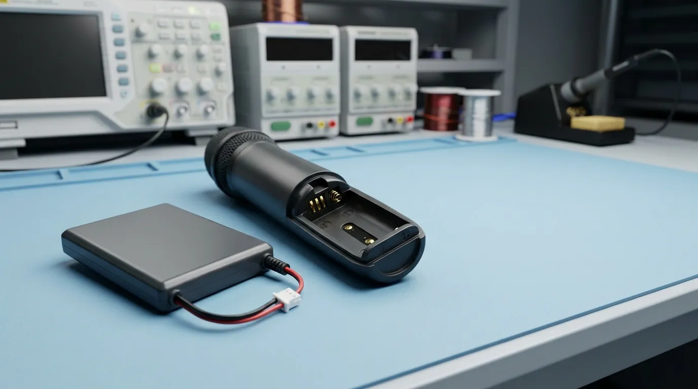
A custom lithium battery for wireless microphones is an application-specific rechargeable pack designed around the microphone's voltage, runtime, load profile, physical envelope, connector, charging method, and protection requirements. A standard AA or 9 V replacement should never be assumed electrically compatible — the lithium cell's nominal voltage and charging profile must match the microphone's electronics and charger design.
For OEMs developing handheld transmitters, bodypack transmitters, or charging cases, a custom pack is the practical path to reliable runtime and safe charging. Gloflux applies the same custom battery development process used for other portable audio products, including a lipo battery for portable speaker and a lipo battery for bluetooth devices, to microphone-specific power requirements.
What "Custom Lithium Battery for Wireless Microphones" Means for an OEM
A custom lithium battery pack is built for a specific device, not pulled from a retail shelf. The OEM defines the electrical interface, mechanical envelope, charging method, and protection requirements. This is fundamentally different from buying a consumer replacement battery, where the device already dictates every parameter.
Wireless microphone systems contain several device types, each with different power demands:
- Handheld transmitters — used for vocals and speech; they need a pack that fits inside the handle and sustains the transmitter's radio, audio processing, and optional display.
- Bodypack transmitters — worn by the user; they prioritize thin, light packs that fit a small cavity and survive movement and handling.
- Receivers — typically mains-powered, but portable or beltpack receivers may need a battery pack.
- Charging cases — contain larger packs that recharge individual transmitters; they require charge-management electronics rather than a simple load.
Each device type changes the battery specification. A bodypack transmitter may need a thin LiPo pouch pack, while a charging case may need a higher-capacity pack with a different charge profile. The same engineering logic applies to a Rechargeable battery for portable audio recorders, where runtime and field use drive the pack design.
Gloflux's customization process is designed around these OEM requirements. The company's published process covers needs assessment, cell sourcing, engineering design, prototype testing, mass production, and after-sales service, and it is directed at OEMs, engineers, and sourcing teams worldwide.
Specifications an OEM Must Provide to a Battery Supplier
A battery supplier cannot design a correct pack from a vague request. The OEM must supply a clear requirement set before any cell selection or pack design begins.
| Requirement | What the Supplier Needs |
|---|---|
| Nominal voltage | Target operating voltage for the microphone electronics |
| Maximum charge voltage | The highest voltage the pack must reach during charging |
| Runtime target | How long the microphone must operate on a full charge |
| Duty cycle | Whether the device transmits continuously or intermittently |
| Continuous current | The sustained current draw under normal operation |
| Peak current | Short-duration current spikes during transmission bursts or startup |
| Capacity | The charge required to meet the runtime target (mAh or Ah) |
| Physical envelope | Dimensions of the battery cavity and available space for the pack |
| Connector and polarity | Connector type, pinout, locking mechanism, and polarity orientation |
| Wiring | Cable length, wire gauge, and exit direction |
| Charging method | Charger connector, charge voltage, charge current, and expected charge time |
| Operating temperature | Separate values for charging, discharging, and storage |
| Protection expectations | Whether basic PCM protection or a smart BMS with balancing and fuel gauging is required |
| Environmental requirements | Drop, vibration, shock, or ingress protection (IP) needs |
| Documentation | Datasheet/TDS, test report, UN38.3 test summary, SDS/MSDS, and any IEC/UL evidence |
The supplier should not be guessing these values. A clear specification reduces prototype iterations and prevents field failures. Gloflux's development process begins with exactly this type of requirements capture — assessing the device's electrical and mechanical constraints before selecting cells or designing the pack.
Li-ion vs LiPo for Wireless Microphone Battery Packs
The chemistry choice depends on the microphone's voltage requirements, available space, current demand, and charging architecture.
| Chemistry | Typical Nominal Voltage | Form Factor | Fit for Wireless Microphone Transmitters |
|---|---|---|---|
| Li-ion (cylindrical) | 3.6–3.7 V per cell | Rigid cylinder (e.g., 18650, 21700) | Suitable where a standard cylindrical cell fits the handle or case |
| Li-ion (prismatic) | 3.6–3.7 V per cell | Rectangular rigid case | Suitable for moderate-thickness cavities |
| LiPo (pouch) | 3.6–3.7 V per cell | Thin, flat pouch; customizable dimensions | Preferred for compact handheld and bodypack transmitters with flat or irregular cavities |
| LiFePO4 | 3.2 V per cell | Cylindrical or prismatic | Requires system-level voltage and charger redesign; usually not the default for small transmitters |
| Ni-MH / AA | 1.2 V per cell | Standard AA | Only relevant where the device's electronics are designed for Ni-MH or primary AA cells |
The correct chemistry is not a preference — it is a consequence of the device's electrical design and physical constraints.
Why Voltage and Charging Compatibility Determine the Correct Chemistry
The most common integration mistake is assuming that any lithium cell can replace a AA battery. According to Audio-Technica, lithium cells are generally not recommended in its wireless systems that require AA batteries because a lithium AA cell can provide a substantially higher voltage than the AA or Ni-MH cell the device was designed for.
This is not a minor difference. A device designed for a 1.2 V to 1.5 V AA cell may be damaged by a 3.6 V to 3.7 V lithium cell. The microphone's electronics, regulator, and charger all assume a specific voltage range.
A custom pack redesign therefore includes a charger review — not just a cell swap. The charger profile must match the pack's chemistry, series count, and voltage limits. If the OEM changes the battery technology, the charging electronics must change with it.
How to Size the Battery Pack: Voltage, Capacity, and Pack Architecture
Sizing a pack requires more than picking a capacity value. The OEM must know the device's voltage requirement, average load, peak load, and runtime target.
The starting point is the load profile. A wireless microphone transmitter draws current for the radio, audio processing, and any display or backlight. The radio transmission itself can create short current peaks that are higher than the average draw, especially if the device transmits frequently or at higher power.
Runtime is determined by dividing the usable capacity by the average load:
Runtime (hours) ≈ Usable capacity (mAh) ÷ Average load (mA)For example, if a transmitter draws an average of 100 mA and the pack provides 1,000 mAh of usable capacity, the calculated runtime is approximately 10 hours. The usable capacity is lower than the rated capacity because the pack cannot be discharged to zero — the BMS or device electronics will cut off at a defined minimum voltage.
The pack's series count (S) determines the voltage. A 1S pack has a nominal voltage of approximately 3.6–3.7 V for Li-ion or LiPo. A 2S pack provides approximately 7.2–7.4 V nominal. The OEM's electronics dictate which S-count is required.
The parallel count (P) increases capacity and available current. A 2P configuration doubles the capacity of a 1P configuration at the same voltage. Parallel cells also share the current load, which can reduce voltage sag under peak demand.
Voltage sag is the drop in pack voltage under load, driven largely by internal resistance. A high-capacity cell can still fail to hold voltage if its internal resistance is high relative to the current demand. This matters for wireless microphones because a voltage sag below the device's cutoff can cause resets, audio interruption, or a false low-battery indication.
The pack must therefore be specified for both energy (capacity) and power (current capability), not just one or the other.
Pack Integration: Connector, Enclosure, Wiring, and Thermal Design
The battery does not exist in isolation — it must fit into a compact microphone body and survive daily handling.
Connector selection is one of the first integration decisions. The connector must match the device's PCB interface, carry the required current, and resist accidental disconnection during use. Polarity must be unambiguous. A locking connector may be necessary for bodypack transmitters that move with the user.
Wiring must be sized for the current draw and routed to fit the cavity. Wire gauge affects both current capacity and voltage drop. A thin wire may suffice for low current, but a poor choice adds resistance and heat.
Enclosure design depends on the cell format. Pouch cells, which are common in compact transmitters, can swell slightly over their life. The enclosure must allow for this dimensional change without stressing the cell or cracking the housing. Hard-shell enclosures, tape-wrapped packs, and potting each suit different assembly processes.
Thermal design matters more than it appears. A tight cavity traps heat during charging and high-current operation. The pack's thermal path — through the enclosure, connector, and surrounding structure — affects both safety and cycle life. If the microphone is used in warm environments or direct sunlight, the thermal margin shrinks further.
Gloflux's custom battery process includes the mechanical design of the pack — enclosure, connector, and wiring — as part of the engineering scope, not as an afterthought.
BMS, Protection, and Charger Coordination
A custom lithium pack needs protection, and the protection level depends on the pack's architecture and the device's requirements.
PCM (Protection Circuit Module) provides basic protection against overcharge, over-discharge, overcurrent, and short circuit. Most consumer packs include a PCM. It is the minimum safety layer.
BMS (Battery Management System) is a broader term. A conventional BMS adds cell balancing for multi-cell series packs, ensuring that each cell stays within its voltage range. A smart BMS adds fuel gauging, state-of-charge estimation, communication (such as SMBus, I2C, UART, CAN, RS485, or Bluetooth), and data logging.
A wireless microphone transmitter does not automatically need a smart BMS. The decision depends on whether the device must report remaining runtime, whether the pack has multiple cells in series, and whether the OEM wants data for diagnostics.
Charger coordination is essential. The charger must match the pack's chemistry, series count, charge voltage, and charge current. A typical lithium charge profile uses CC/CV — constant current until the cell reaches its charge voltage, then constant voltage while current tapers. A charger designed for a different chemistry or S-count will either undercharge the pack or damage it.
Gloflux's custom battery development process includes BMS and protection design as part of the pack engineering. The exact protection thresholds and BMS features should be defined during requirements capture, not assumed.
Testing and Documentation an OEM Should Request
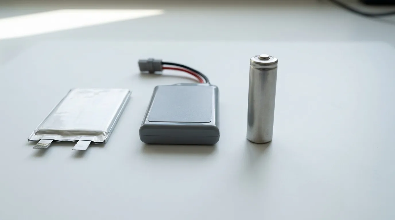
A prototype approval should never be based on a sample that "looks fine." The OEM needs a defined test plan and documented evidence.
| Document or Test | Purpose | When It Matters |
|---|---|---|
| Capacity test | Verifies the pack delivers its rated capacity under defined conditions | Every prototype and production batch |
| Cycle/aging test | Shows how capacity degrades over repeated charge/discharge cycles | Design validation |
| Charge-profile test | Confirms the charger works correctly with the pack's protection system | Design validation |
| Vibration/shock/drop tests | Simulates portable-use handling and transport | Design validation for bodypack and handheld transmitters |
| Temperature-range test | Confirms operation within the intended environment | Design validation |
| UN38.3 test summary | Documents that the lithium battery design passed the UN transport tests | International shipment of lithium batteries |
| IEC/UL report | Provides product-safety evidence for a defined model and standard scope | Market access and safety compliance |
| SDS/MSDS | Documents chemical, safety, and handling information | Logistics and safety compliance |
| Datasheet/TDS | States the pack's electrical and mechanical specifications | Design and procurement documentation |
The transport rules for lithium batteries depend on the battery's configuration and watt-hour rating. According to the International Air Transport Association (IATA), lithium batteries are subject to specific transport requirements, and spare lithium batteries are not allowed in checked baggage. The U.S. Department of Transportation's Pipeline and Hazardous Materials Safety Administration (PHMSA) provides guidance on lithium-battery test summaries under the UN 38.3 framework.
An IEC/UL report is not the same as a UN38.3 test summary. An IEC/UL report applies to a defined model, construction, and standard scope. A UN38.3 test summary documents transport testing. A company's ISO 9001 certificate is a quality-system certificate, not a product certificate.
The OEM should request the test plan and the test report before approving the prototype — not after production starts. Model-specific documentation, traceability, and change control matter for consistent long-term supply.
How to Evaluate a Custom Battery Supplier
The final step is a structured supplier evaluation. The battery partner should be able to demonstrate more than a low price and a fast sample.
Require a specification-review process. The supplier should ask about the device's load profile, voltage, runtime, charging, mechanical envelope, and documentation needs before quoting a price.
Request a test plan and report for the prototype — not just a sample. The report should state the test methods, conditions, and results.
Confirm the cell source and the change-control policy. Cell substitutions are a common failure point. The supplier should agree to notify the OEM of any cell, BMS, connector, or enclosure change before it happens.
Verify traceability. The OEM should be able to trace a production batch back to its components and test records.
Agree on development gates — prototype approval, pilot run, and mass production. Each gate should have defined acceptance criteria.
Clarify commercial terms — MOQ, tooling, lead time, and warranty — before committing to production.
Confirm documentation scope. The supplier should provide the datasheet/TDS, SDS/MSDS, UN38.3 test summary, and any IEC/UL evidence for the exact model, not a generic "we have certifications" statement.
Gloflux's published process includes prototype testing and mass production as defined stages, and the company states that it works directly with OEMs, engineers, and sourcing teams. The supplier evaluation should test whether the process is real in practice — ask for the model-specific documentation and the test plan.
Start Your Custom Wireless Microphone Battery Project
The path to a reliable wireless-microphone battery pack is straightforward: define the device's voltage, load profile, runtime, mechanical envelope, charging method, and protection requirements; select the chemistry and pack architecture that match; validate the prototype against a defined test plan; and confirm the documentation before production.
If you are designing a wireless microphone and need a custom lithium battery pack, submit your requirement sheet to Gloflux for a custom pack review. The development process — from needs assessment through engineering design, prototype testing, and mass production — is built for exactly this type of OEM project.
Talk to the Manufacturer
Resources & Insights

High Capacity Lithium Battery for Wearables: High-Voltage LiPo Cell Design
2026-10-19

Cylindrical Battery Packs for Laptops: 2S vs 3S vs 4S Battery Design
2026-10-19

Stage Lighting Battery Pack: Prevent Voltage Drop & LED Flicker
2026-10-19

Best Rechargeable Batteries for Smart Devices: Performance, Safety, and Selection Guide
2026-10-19


