


 Home /
 NTC Thermistor for Lithium Battery Packs: Selection and Placement Guide


Table of Contents
- What Is an NTC Thermistor?
- How a BMS or Charger Reads the NTC
- NTC Selection Criteria
- Where to Place the NTC
- One Sensor or Several?
- Mechanical Integration and Wiring
- Validation and Testing
- Common NTC Mistakes and How to Avoid Them
- NTC vs. PTC vs. Other Temperature Sensors
- RFQ Checklist for a Custom Battery Pack with NTC
- References
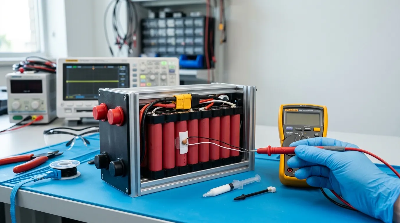
An NTC thermistor (negative temperature coefficient thermistor) is a temperature-dependent resistor whose resistance decreases as temperature rises. In a lithium battery pack, it provides temperature feedback to a BMS or charger, which may reduce current, suspend charging, limit operation, or trigger protection. The correct NTC value and placement depend on the receiving circuit, target temperature window, cell chemistry, pack construction, and thermal hot spots—not on a universal standard.
This guide covers the complete process: how the NTC interface works, which specifications matter, where to place the sensor for meaningful readings, how many sensors you need, and what to include in a custom battery pack RFQ. For broader context on how this fits into the overall custom battery pack design process, see the parent guide.
What Is an NTC Thermistor?
An NTC thermistor is a resistor whose resistance decreases predictably as its temperature increases. This negative temperature coefficient is what makes it useful for temperature sensing in battery packs.
NTC vs. PTC: A PTC (positive temperature coefficient) thermistor behaves in the opposite direction—resistance increases as temperature rises. PTCs are commonly used for overcurrent limiting or self-resetting fuses, not for linear temperature measurement. In battery packs, NTCs are the standard choice when the goal is continuous temperature monitoring.
A critical distinction: the NTC is a sensing element, not a protection device. It does not cut off power or disconnect the battery. It produces a resistance signal that the BMS or charger interprets and acts upon.
How a BMS or Charger Reads the NTC
The NTC thermistor is part of a voltage divider circuit. A bias resistor (inside the BMS or charger) is connected in series with the NTC, and the voltage at their junction is read by an analog-to-digital converter (ADC). As the NTC resistance changes with temperature, the divided voltage changes, and the ADC converts that voltage into a temperature value.
Texas Instruments explains that several factors affect measurement accuracy: NTC thermistor linearity, resistance tolerance, bias-resistor drift, and ADC resolution all contribute to the final temperature reading [1].
The critical implication is that NTC values are circuit-specific. A charger or BMS manufacturer designs the voltage divider around a particular NTC curve—typically defined by a resistance value at 25°C (R25) and a beta value. For example, Analog Devices specifies a 100 kΩ-at-25°C thermistor with a defined beta value for its LTC4061 charger's temperature-sense (TS) input, with a usable temperature window of 0–50°C for that specific circuit [2].
This means you cannot assume a 10 kΩ NTC—the most common commercial value—will work with every BMS or charger. If the input circuit is designed for a 100 kΩ curve and you install a 10 kΩ NTC, the inferred temperature will be wrong, and the charger may reject the pack or terminate charging early.
The BMS or charger uses the temperature reading to make decisions:
- Suspend charging if the pack is too cold or too hot
- Reduce charge current in extreme conditions
- Limit discharge current during overtemperature events
- Trigger a protection response (such as opening a FET) outside the safe window
For detailed information on BMS architecture and protection thresholds, see our guide on custom battery bms.
NTC Selection Criteria

When specifying an NTC for a lithium battery pack, the following parameters define the component:
| Parameter | What It Means | What to Check | Why It Matters |
|---|---|---|---|
| R25 | Resistance at 25°C (e.g., 10 kΩ, 100 kΩ) | Match the BMS or charger input circuit specification | The circuit is designed around a specific R25 |
| Beta value (B) | Constant that defines the shape of the resistance-temperature curve | Must match the BMS/charger algorithm | Two NTCs with the same R25 but different beta values diverge significantly away from 25°C |
| R25 tolerance | Allowable deviation from the nominal resistance at 25°C | Typically ±1% to ±5% | Directly affects the temperature error at 25°C |
| Beta tolerance | Allowable deviation in the beta constant | Typically ±0.5% to ±3% | Affects accuracy across the entire operating range |
| Operating temperature range | Minimum and maximum temperature the NTC can withstand | Must cover charge, discharge, and storage conditions | Exceeding the range may cause permanent resistance drift |
| Thermal time constant | Time to reach 63.2% of a step temperature change | Match to the expected thermal transient speed | A slow sensor may miss fast heating events |
| Package and mounting | Through-hole, SMD, insulated lead, ring terminal, adhesive-backed | Must suit the cell format and mechanical design | Affects thermal coupling and electrical isolation |
| Insulation | Bare lead vs. insulated lead vs. encapsulated body | Must prevent short circuits against cells or enclosure | A bare lead touching a cell terminal creates a false reading or a short |
The selection process is straightforward:
- Read the BMS or charger datasheet to find the required R25, beta value, and temperature window
- Choose an NTC that matches the full curve, not just R25
- Verify tolerances are acceptable for your accuracy requirement
- Confirm the operating temperature range covers your application
- Select a package and insulation that suit your mechanical design
Worked example (circuit-specific): The LTC4061 charger datasheet specifies a 100 kΩ-at-25°C thermistor (Vishay NTHS0603N02N1002J) with a beta of 3500 K, and a charge-temperature window of 0–50°C [2]. If your pack uses a different NTC with the same R25 but a beta of 4000 K, the temperature estimate will diverge as the pack heats or cools, potentially triggering false protection.
Do not choose an NTC because a value is common. Choose it because it matches the circuit that will read it.
Where to Place the NTC
Placement is a thermal-design decision, not a universal rule. The same NTC can produce misleading readings depending on where it sits in the pack.
| Placement Objective | Where to Place | Caveat | When to Use It |
|---|---|---|---|
| Cell surface temperature | Directly on a cell side wall, using thermally conductive but electrically insulating adhesive | Represents the temperature of that specific cell only | Most common objective; the BMS/charger expects a representative cell temperature |
| Hot-spot detection | At the highest-temperature location: current interconnects, busbars, center of a parallel group | The reading reflects the local hot spot, not average pack temperature | Use when the BMS algorithm is designed to act on hot-spot temperature |
| Busbar area | Near a busbar or interconnect | Will read hotter than the cell surface under high current; do not confuse with cell temperature | Useful for detecting connection degradation, not general pack temperature |
| Cooling plate interface | On the cooling surface | May read cold even when the cell is hot—the plate cools the sensor faster than the cell | Only if the circuit intentionally monitors cold-side temperature |
| Enclosure or ambient | On the enclosure wall or in free air | Measures environmental temperature, not cell temperature | Only if the BMS/charger uses an ambient reference |
Analog Devices explicitly states that battery temperature is measured by placing the NTC close to the battery pack [2]. This is the standard approach, but "close" is not enough—the sensor must be in good thermal contact with the surface whose temperature you intend to measure.
Form-factor considerations:
- Cylindrical cells (18650, 21700): The cell side wall is accessible. Use a thermally conductive adhesive, a clip, or a ring terminal. Avoid a location exposed to direct airflow, which may cool the sensor below the cell surface temperature.
- Pouch cells: The flexible pouch surface requires a thermal pad or soft adhesive that does not indent or stress the cell. Avoid placing the sensor over the seal edge. Account for cell swelling, which can change contact pressure.
- Prismatic cells: The rigid case surface works well. Be aware of busbar proximity—a sensor near the terminal may read a hot-spot temperature rather than the case average.
Thermal coupling and response time: The NTC must be in good thermal contact with the measured surface. Air gaps and thick adhesive layers add thermal resistance and increase the thermal time constant—the sensor will respond slowly and may miss transient heating events. Use the thinnest practical layer of thermally conductive, electrically insulating material.
For high-current mobility applications where thermal gradients are significant, such as e-scooter battery packs, the placement strategy becomes even more critical. In a high-discharge application like a Custom lithium ion battery for scooter, a single NTC on one cell may not capture the worst-case hot spot that develops under sustained acceleration or hill climbing.
One Sensor or Several?
A single NTC measures the temperature of the cell or location where it is attached. It does not represent the entire pack.
| Situation | Recommended Approach | Why |
|---|---|---|
| Small pack (1–2 cells), low current, stable thermal environment | 1 sensor | One cell surface is representative |
| Medium pack, moderate current, some thermal gradient | 2 sensors (e.g., one cell surface, one hot spot) | Captures the most important variation |
| Large pack, high current, wide temperature range | Multiple sensors on cells, busbars, or both | Thermal gradients are significant; a single sensor may miss the worst-case condition |
| Any pack with BMS channels available | Use as many sensors as the BMS algorithm can read and act on | Unused sensor channels are wasted diagnostic capability |
The number of sensors should match the pack's thermal complexity and the BMS's input capacity. Adding sensors increases cost, wiring, test time, and potential failure modes. Omitting sensors on a high-current pack risks missing a local hot spot that could indicate cell imbalance or connection degradation.
Mechanical Integration and Wiring
The electrical and mechanical connection of the NTC is as important as the component selection.
- Polarity: Ensure correct wiring of the NTC leads. A reversed connection may produce an open or shorted circuit, which the BMS/charger may interpret as a fault.
- Strain relief: Secure the leads near the sensor and at the connector. Vibration can fracture solder joints or cause intermittent contact.
- Insulation: Use insulated leads where they could contact cells, busbars, or the enclosure. A bare lead against a cell terminal creates a false reading or a short.
- Mechanical retention: Adhesive, clip, ring terminal, or potting—choose the method that provides good thermal contact without stressing the cell. Adhesives must be thermally conductive and electrically insulating.
- Lead routing: Avoid routing leads near high-current conductors without sufficient insulation. Induced noise or localized heating can corrupt the signal.
- Self-heating: The measurement current through the NTC generates a small amount of heat. This is usually negligible, but in a poorly coupled sensor in free air, self-heating can bias the reading.
A clean integration checklist:
- Verify the sensor is electrically isolated from all conductive parts.
- Confirm the lead connection matches the BMS/charger connector pinout.
- Apply strain relief at both ends of the lead.
- Use thermally conductive, electrically insulating adhesive or thermal pad.
- Route leads away from high-current paths.
- Confirm the sensor body is not exposed to airflow that would cool it below the measured surface.
Validation and Testing
The placement and thresholds must be verified under real operating conditions.
| Validation Step | What to Verify | Why It Matters |
|---|---|---|
| Charge at temperature limits | BMS/charger suspends or terminates charging outside the programmed window | Confirms the NTC signal triggers the correct protection response |
| High-current discharge | Temperature reading rises as expected; no false fault | Confirms the sensor is in good thermal contact and the response time is adequate |
| Open-sensor fault | BMS/charger detects an open circuit (often read as a very low or high temperature) | Prevents a disconnected sensor from disabling protection |
| Shorted-sensor fault | BMS/charger detects a short (often read as an extreme temperature) | Prevents a shorted sensor from masking an overtemperature event |
| Ambient extremes | Reading tracks the reference sensor within tolerance | Confirms the NTC and circuit perform across the required range |
| Repeated cycling | No drift, intermittent faults, or mechanical loosening | Confirms long-term reliability of the attachment and wiring |
Record for each validation run: actual R25, beta, measured temperature vs. a reference sensor, thermal time constant, and the BMS/charger response.
Documentation type distinctions:
- A UN38.3 test summary supports transport of a defined lithium battery type. It does not validate NTC accuracy or placement. For detailed guidance on testing and quality control, see our lithium battery quality control and testing guide.
- An IEC/UL test report applies to a defined model, construction, and standard scope. It provides safety validation for the product as built, not proof that the NTC senses temperature accurately at every location.
Common NTC Mistakes and How to Avoid Them
| Mistake | Consequence | How to Avoid |
|---|---|---|
| Choosing an NTC by R25 alone | Incorrect temperature readings away from 25°C | Match beta value and the full curve to the BMS/charger |
| Assuming 10 kΩ is universally compatible | Charger rejects pack or triggers false protection | Read the BMS/charger datasheet for the required NTC curve |
| Placing the sensor in air | Measures ambient, not cell temperature | Use thermally conductive adhesive or direct contact |
| Placing the sensor on a cooling plate | Reads cold even when the cell is hot | Place on the cell surface unless the circuit intentionally uses a cold-side reference |
| Loose thermal contact | Slow response, erratic readings | Use proper adhesive or mechanical retention |
| Routing leads uninsulated near high current | Noise, shorts, hot-spot damage | Insulate and route away from high-current paths |
| Using one sensor for a large pack | Misses local hot spots | Use multiple sensors matched to thermal gradients and BMS channels |
| Confusing pack temperature with cell temperature | Incorrect protection decisions | Define the measurement objective before placing the sensor |
| Treating a transport test as sensor validation | False confidence in accuracy | Validate the sensor with a reference temperature test |
NTC vs. PTC vs. Other Temperature Sensors
| Sensor Type | Output | Linearity | Accuracy | Typical Battery-Pack Use |
|---|---|---|---|---|
| NTC thermistor | Resistance decreases with temperature | Nonlinear (compensated by beta curve) | Good (±1–3°C with matched curve) | Standard temperature sensing for BMS and chargers |
| PTC thermistor | Resistance increases with temperature | Nonlinear and steep | Not used for linear measurement | Overcurrent limiting, self-resetting fuses |
| RTD | Resistance increases nearly linearly | Excellent | Very good (±0.1–0.5°C) | High-accuracy industrial systems; larger and more expensive |
| Digital sensor (1-Wire, I2C) | Digital temperature value | Linearized internally | Very good (±0.5–1°C) | Smart packs with a compatible host interface |
NTCs remain the standard for battery packs because they are small, inexpensive, and require only a simple voltage-divider circuit on the BMS or charger.
RFQ Checklist for a Custom Battery Pack with NTC

When requesting a custom battery pack, the RFQ must include the NTC specification so the manufacturer can integrate the correct sensor.
| RFQ Requirement | What to Specify | Why It Matters |
|---|---|---|
| NTC curve | R25, beta value, R25 and beta tolerance, temperature range | The manufacturer must source a matching component |
| BMS/charger input | Bias-resistor value, TS window, ADC resolution | Confirms the NTC curve is compatible with the protection circuit |
| Sensor type and package | Insulated lead, ring terminal, SMD, adhesive-backed | Defines the physical integration |
| Wiring | Wire gauge, length, connector type, polarity, strain relief | Prevents mechanical and electrical failures |
| Placement | Cell surface, hot-spot, busbar, cooling interface, or ambient | Defines the measurement objective |
| Number of sensors | One, multiple, or per-cell-group; must match BMS channels | Ensures adequate coverage without exceeding input capacity |
| Test evidence | Measured R25, beta, thermal response, BMS/charger fault response, final test report | Verifies the integrated design works |
| Documentation | Datasheet/TDS, UN38.3 test summary, IEC/UL reports, traceability | Provides the compliance and quality evidence |
At Gloflux, we offer custom battery pack development and can include optional NTC thermistors for temperature monitoring and protection as part of the design. Our customization process covers cell selection, pack architecture, BMS integration, and mechanical design—including where and how the NTC is mounted. For a complete discussion of your thermal-monitoring requirements, or to review how NTC integration affects your pack design, contact us with your application details.
References
- Texas Instruments, "Using Thermistors to Enhance Thermal Protection for Battery Management Systems," TI Application Note SNIA032
- Analog Devices, "Standalone Linear Li-Ion Battery Charger with Thermistor Input," LTC4061 Datasheet
Talk to the Manufacturer
Resources & Insights

High Capacity Lithium Battery for Wearables: High-Voltage LiPo Cell Design
2026-10-19

Cylindrical Battery Packs for Laptops: 2S vs 3S vs 4S Battery Design
2026-10-19

Stage Lighting Battery Pack: Prevent Voltage Drop & LED Flicker
2026-10-19

Best Rechargeable Batteries for Smart Devices: Performance, Safety, and Selection Guide
2026-10-19


