


 Home /
 Custom Battery BMS and Communication Options for OEM Products


Table of Contents
- What Is a Battery Management System?
- Basic Protection BMS
- Smart BMS
- Cell Balancing Options
- Fuel-Gauge Functions
- Common Battery Communication Options are wire, metal mesh, and liquid electrolyte.
- UART
- I²C
- SMBus
- CAN Bus
- RS485
- Bluetooth Communication
- Battery Authentication
- How to Choose the Right BMS
- Custom BMS Development Process
- Custom Battery Support From GLOFLUX
- Conclusion
- Frequently Asked Questions
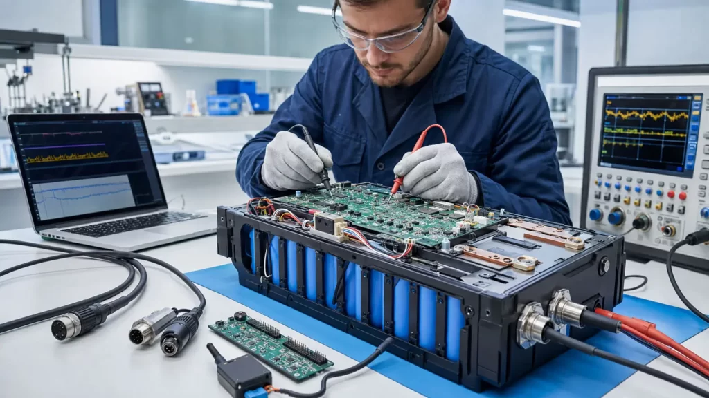
A battery management system is more than a protection circuit. The BMS in a custom battery pack keeps a watch on battery operating conditions, safeguards the cells, regulates charging and discharging, determines battery capacity and, if needed, can communicate with the external battery device.
Correct BMS design is based on the battery chemistry, series configuration, working current, peak load, charger, operating temperature and product-control requirement. Very basic protection might be required for a simple portable device while a medical device, robot or industrial system may need fuel gauging, data logging and real-time communications.
What Is a Battery Management System?
BMS is a device that controls the rechargeable cells in a battery pack. It serves the main task to maintain the battery within certain limits of voltage, current and temperature.
Depending on the application, a custom battery BMS may include:
- Overcharge protection
- Over-discharge protection
- Overcurrent protection
- Short-circuit protection
- Temperature monitoring
- Cell balancing
- Charge and discharge control
- State-of-charge estimation
- State-of-health monitoring
- Cycle-count recording
- Fault history
- Device communication
- Battery authentication
All these functions are not required for every project. Unnecessary features cause PCB size expansion, development and unit cost. The BMS should be based on the actual product requirements.
Basic Protection BMS
A basic protection BMS is the most popular BMS type in portable electronics, lighting applications, speakers, beauty devices and other applications that don't require battery data exchange with host computers.
It normally monitors:
- Individual cell voltage
- Pack current
- Battery temperature
- Charging and discharging status
When a value is reached above the set limit, the protection circuit will switch off the charge or discharge line.
The settings should be the same as the selected cells and application. If the protection is set too low, normal peak load conditions could result in unexpected shutdowns. If it is set too high, it may not give you the protection you're looking for.
Smart BMS
A smart BMS is a combination of protection functions and monitoring, calculation, storage and communication features.
It can include information to the host device like:
- Pack voltage
- Individual cell voltage
- Charge or discharge current
- Remaining capacity
- Battery percentage
- Temperature
- Cycle count
- Estimated runtime
- Fault status
- Manufacturing data
The common applications of smart battery pack include medical devices, robot, AGV, industrial equipment and P.O.S/Professional portable system.
Cell Balancing Options
Differences in voltage and capacity may occur over a period of time between cells connected in series. To minimize these disparities and maximize the useable capacity of the pack, they can be balanced.
Passive Balancing
Passive balancing takes energy from the higher voltage power cells, typically in the form of heat, via resistors. It is comparatively simple, compact and is extensively utilized in custom battery packs.
Active Balancing
Active Balance – transfers energy from one cell to another rather than dissipates it. May be used for larger or higher dollar battery systems where balancing efficiency is a concern.
The type of balancing will vary based on cell count, capacity, expected imbalance, available space, thermal design and project cost.
Fuel-Gauge Functions
A Fuel gauge helps to estimate the amount of battery life that still remains. Measuring voltage is not sufficient since voltage to state of charge varies with chemistry, temperature, current and battery age.
Fuel-gauge systems may use:
- Coulomb counting
- Voltage measurement
- Current measurement
- Temperature compensation
- Cell-model algorithms
- Learning and calibration data
If an accurate battery percentage or remaining operation time is required for the device, the selection and calibration of the fuel gauge should be carried out during product development.
Common Battery Communication Options are wire, metal mesh, and liquid electrolyte.
Some communication protocols are appropriate for some devices and some are not. The host controller and the battery BMS should have the same voltage, data format, command and connectors.
UART
In many embedded products, UART is a very simple serial communications method. Can pass: battery voltage, battery current, battery temperature, battery capacity, battery fault data from BMS to host controller and vice versa.
UART can be used when:
- Communication distance is short
- The device uses a simple point-to-point connection
- Low implementation cost is important
- The host controller has an available UART interface
It's up to an engineer to ensure that baud rate, voltage level, data frame and command format are correct.
I²C
I2C is a two-line clock-line and data-line communication protocol and it is widely used to communicate between ICs within a short distance.
It could be useful for small electronics where the battery and host controller are near each other. Design considerations include address selection, pull-up resistance, voltage level and electromagnetic interference.
SMBus
SMBus is a subset of the I²C protocol, but it also specifies extensions to the protocol for system management. It is commonly known as smart batteries in laptops, medical devices and professional portable devices.
A smart battery employing SMBus can offer:
- Remaining capacity
- Full-charge capacity
- Battery voltage
- Current
- Temperature
- Cycle count
- Charging requests
- Alarm status
The battery, charger and device must support compatible commands and data definitions.
CAN Bus
CAN is a powerful differential communications system that is widely employed in vehicles, robots, AGVs, industrial machines and energy systems.
CAN may be selected when:
- The electrical environment contains noise
- Communication distance is longer
- Multiple controllers share a network
- Reliable error detection is required
- The battery must communicate with a motor controller or central control unit
The communication method is defined by CAN, but the project requires a compatible message map, baud rate, identifiers and application-layer data format.
RS485
RS485 is a differential physical-layer standard for longer distances and electrically noisy applications. It is often used in industrial systems, stationary equipment and energy-storage products.
An agreed communication protocol – such as a custom command structure or Modbus based implementation – is also a part of a complete RS485 solution.
RS485 can be used when there are multiple battery modules to talk to the master controller.
Bluetooth Communication
Technicians or users can access battery info using a mobile application via Bluetooth. Depending on the design, the app may display voltage, current, temperature, capacity, cycle count and fault data.
Before adding Bluetooth, OEM teams should consider:
- Cybersecurity
- User permissions
- Firmware updating
- Mobile application maintenance
- Pairing method
- Data privacy
- Standby power consumption
If there is no monitoring or service requirement for the product, Bluetooth should not be added as a marketing device.
Battery Authentication
Some high-value or replaceable battery packs employ authentication to assist the device to discover an authorized battery.
Authentication can support:
- Accessory compatibility
- Counterfeit prevention
- Service tracking
- Warranty management
- Product configuration
- Controlled charging parameters
The implementation can be through a security IC or a digital key/challenge-response approach. Defining requirements for authentication requirements right from the start is important, as it influences work on battery and host-device development.
How to Choose the Right BMS
Before OEM team develops BMS, confirm the following information:
- Battery chemistry
- Series and parallel configuration
- Nominal and maximum voltage
- Continuous discharge current
- Peak current and duration
- Charging current
- Operating temperature
- Number and position of temperature sensors
- Balancing requirements
- Fuel-gauge accuracy
- Communication protocol
- Connector pinout
- Fault response
- Sleep-current target
- Certification requirements
Additionally, the BMS needs to be tested within the actual device. Current spikes may not occur during standard lab tests, but they can happen with the motors, wireless modules, heaters (and other loads).
Custom BMS Development Process
A typical custom BMS project includes:
- Review the battery and device requirements
- Select the protection and monitoring components
- Define voltage, current and temperature limits
- Confirm the communication protocol
- Design the schematic and PCB
- Develop firmware when required
- Produce prototype boards
- Assemble sample battery packs
- Test protection and communication functions
- Validate the battery inside the device
- Freeze the approved hardware and firmware versions
- Begin pilot and mass production
All critical settings should be documented to maintain consistency between samples and production batteries.
Custom Battery Support From GLOFLUX
GLOFLUX offers a flexible BMS integration solution for Lithium-Ion, Lithium-Polymer and LiFePO4 battery packs. This can vary from protection circuits, balancing systems, fuel gauging, monitoring systems, communication and battery enclosure integration, etc.
Applications include:
- Medical equipment
- Service robots
- AGVs and AMRs
- Industrial systems
- POS terminals
- Smart devices
- Portable lighting
- Replaceable battery modules
The customers can submit the device specification, communication document, connector definition or existing battery sample for technical evaluation.
Conclusion
Not all battery management systems are created equal, and the functionality doesn't make the best one. It is the one which safely carries the selected cells, operating current, charger, device controller and requirements of services.
Simple portable protection may be adequate for a simple portable product. For medical or professional devices, the use of smart monitoring and SMBus might be suitable, while CAN or RS485 might be more appropriate in robots and industrial systems. The requirements are identified in advance, avoiding hardware conflicts and firmware delays and unexpected product shutdowns.
Frequently Asked Questions
1. Does every custom battery need a BMS?
Generally rechargeable multi-cell battery packs need appropriate protection and management, the circuit design for which will be dependent on the rechargeable battery chemistry, configuration and application.
2. Which communication protocol is best for a smart battery?
There is no one right answer. UART and I²C are good for short on-board wiring, SMBus is used for smart battery applications, and for industrial systems, CAN or RS485 is often used.
3. Can a BMS display the remaining battery percentage?
Yes. A smart BMS, together with an appropriate fuel-gauge system, can calculate the SoC and communicate the results to the host device.
4. Can GLOFLUX match an existing communication protocol?
Older commands, message maps and battery samples can be analysed to see if there is a suitable customised BMS that can be created.
5. Can the BMS settings be changed after sampling?
It is important to note that settings can be changed during prototype testing, but hardware, firmware and protection parameters should be fixed prior to certification and mass production.
Talk to the Manufacturer
Resources & Insights

High Capacity Lithium Battery for Wearables: High-Voltage LiPo Cell Design
2026-10-19

Cylindrical Battery Packs for Laptops: 2S vs 3S vs 4S Battery Design
2026-10-19

Stage Lighting Battery Pack: Prevent Voltage Drop & LED Flicker
2026-10-19

Best Rechargeable Batteries for Smart Devices: Performance, Safety, and Selection Guide
2026-10-19


