


 Home /
 Lithium Battery for Heated Tobacco Devices: OEM Power and Charging Design


Table of Contents
- How a Heated Tobacco Device Uses Its Battery
- The OEM Battery Design Process for Heated Tobacco Devices
- Battery Cell vs Battery Pack: What the OEM Must Specify
- Choosing Battery Chemistry and Form Factor
- Electrical Specifications for the Heated Load
- Protection, BMS, and Charger Coordination
- Thermal and Mechanical Integration
- Sample Validation and Production Documentation
- What to Ask a Heated Tobacco Battery Supplier (RFQ Checklist)
- Safety and Common Design Mistakes to Avoid
- Battery Documentation and Transport Compliance at a Glance
- Building a Reliable Heated Tobacco Battery Specification
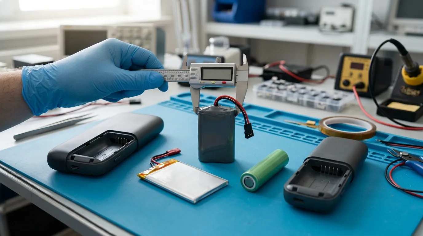
A lithium battery for heated tobacco devices is a rechargeable battery pack engineered to power the device's heating chamber and control electronics within strict voltage, pulse-current, thermal, and dimensional constraints. For OEMs, the design challenge is translating the heater's load profile into a complete battery specification that includes cell selection, pack architecture, protection circuitry, charger coordination, and the documentation required for global shipment and market access.
Heated tobacco devices differ from e-cigarettes in a critical way: they heat a tobacco stick or pod to a precise temperature to generate aerosol, rather than atomizing a liquid at high power for extended periods. The heating element draws significant current in short pulses, which changes how the battery must be specified, protected, and charged. For a broader comparison of battery applications across vaping and heated products, see our guide to the lithium ion battery for e-cigarettes or explore how compact devices use different cell formats in our article on the lithium polymer battery for disposable vape devices.
How a Heated Tobacco Device Uses Its Battery
A heated tobacco device contains a heating chamber, control electronics, a rechargeable battery, and a housing. The battery performs two distinct jobs:
- It supplies pulse current to the heating element during a session.
- It powers the control electronics, display, and communication features between heating pulses.
The heater is the dominant load. Because it operates in pulses rather than continuously, the battery must deliver a high peak current for short durations, then recover while the device regulates temperature. This pulse profile affects voltage stability, heat generation, and the long-term cycle life of the pack.
The load profile for heated tobacco is different from that of an e-cigarette atomizer. An atomizer may draw a steadier current while the user inhales, whereas a heated tobacco heater cycles on and off to maintain a target temperature. An OEM must therefore specify a battery that supports the heater's pulse current, not just the average power consumption.
The OEM Battery Design Process for Heated Tobacco Devices
Designing a battery for a heated tobacco device requires a structured workflow that starts with device requirements, not with a battery catalogue. A reliable process follows these steps:
- Define the load profile. Determine the heater resistance, the target heating temperature, the pulse current during heating, the pulse duration, the number of pulses per session, and the number of sessions between charges.
- Establish runtime and recharge targets. Define how many sessions the user should get per charge and how quickly the device must recharge.
- Translate the load into electrical requirements. Calculate the voltage range, capacity, energy, continuous current, and peak pulse current the pack must supply.
- Choose the chemistry and cell format. Select between Li-ion and Li-polymer chemistry and between cylindrical, pouch, or custom-shaped cells based on the device envelope, energy density, and current capability.
- Design the pack architecture. Determine the series and parallel cell configuration, then select the protection circuit or battery management system (BMS).
- Specify mechanical and thermal integration. Define enclosure, insulation, connector, wiring, and thermal management requirements relative to the heater's proximity.
- Define the charger interface. Match the charger's voltage, current, and connector to the battery chemistry and pack configuration.
- Validate with prototypes. Test electrical, thermal, mechanical, and charging performance against the specification.
- Review documentation. Confirm that the supplier provides the datasheet, UN38.3 test summary, SDS/MSDS, and any model-specific safety reports applicable to the final design.
This workflow keeps the battery design tied to measurable device requirements rather than to generic performance claims.
Battery Cell vs Battery Pack: What the OEM Must Specify
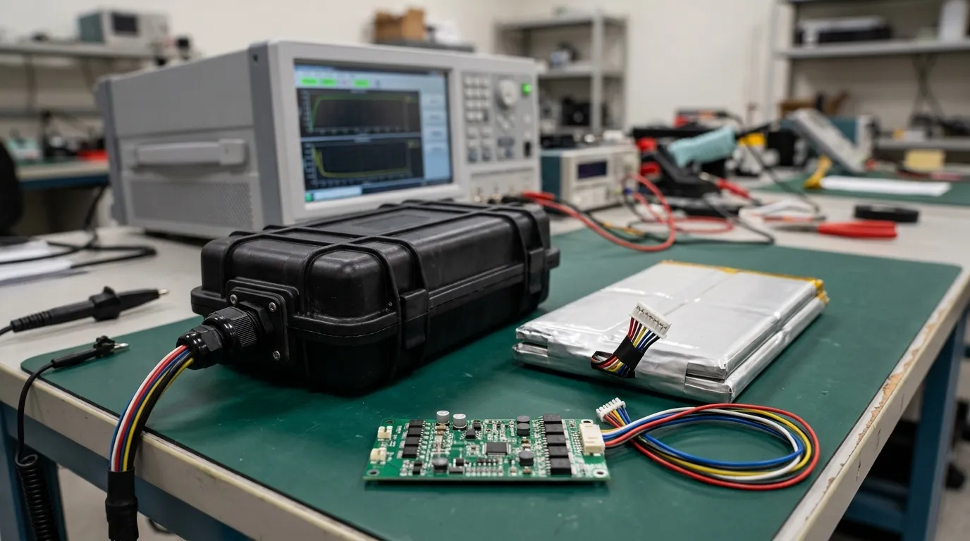
A common mistake in OEM battery sourcing is treating a cell and a complete battery pack as interchangeable. They are not.
A cell is the basic electrochemical unit that stores and releases energy. It has a nominal voltage, capacity, internal resistance, and maximum current rating defined by the cell manufacturer.
A battery pack is the complete power system delivered to the device. It contains one or more cells, a protection circuit or BMS, wiring, a connector, and an enclosure. The pack has its own voltage, capacity, current, temperature, and cycle-life ratings that account for the cells plus the protection and interconnection.
| Specification | Cell | Battery Pack |
|---|---|---|
| Voltage | Cell nominal voltage (e.g., 3.6–3.7 V for Li-ion) | Pack nominal voltage (depends on series cell count) |
| Capacity | Cell capacity in mAh or Ah | Pack capacity in mAh or Ah (depends on parallel cell count) |
| Current | Cell continuous/peak current | Pack current rating including BMS and connector limits |
| Protection | Usually none or minimal | Overcharge, over-discharge, overcurrent, short-circuit, and temperature protection |
| Mechanical | Bare cell | Enclosure, connector, wiring, insulation |
| Documentation | Cell datasheet | Pack datasheet, BMS report, UN38.3 test summary |
For a heated tobacco device, the OEM should specify the complete pack, not a single cell. The pack's protection circuitry, connector, and thermal behaviour are part of the device's safety system. A cell alone cannot be safely integrated into a consumer product.
Choosing Battery Chemistry and Form Factor
The chemistry and form factor determine how the battery fits in the device, how much energy it can store, and how much current it can deliver.
Li-ion vs Li-Polymer
Li-ion (lithium-ion) and Li-polymer (LiPo) batteries share similar electrochemistry but differ in construction and packaging.
| Factor | Li-ion (Cylindrical) | Li-Polymer (Pouch) |
|---|---|---|
| Form factor | Rigid, standardized cylindrical sizes | Thin, flexible, can be shaped to the device |
| Energy density | High | High, but can vary with shape |
| Mechanical strength | Strong metal can | Soft pouch requires rigid support |
| Customization | Limited to standard sizes | Can be custom-shaped for compact devices |
| Protection | Always required | Always required |
| Typical use | High-current, robust applications | Compact, space-constrained devices |
Li-polymer cells are often attractive for heated tobacco devices because the pouch format can be shaped to fit around other internal components. However, a pouch cell needs mechanical protection and thermal management, since it has no rigid can. A cylindrical Li-ion cell offers robust construction and established manufacturing standards, but it imposes fixed dimension constraints.
Cylindrical vs Pouch
- Cylindrical cells (such as the 18650 or 21700 formats) offer high energy density, consistent manufacturing, and good mechanical rigidity. They are a strong choice when the device envelope can accommodate a standard cell diameter and length.
- Pouch cells allow the pack to fit into a thin or irregular cavity. They are lighter and can be designed to maximize space, but they require more careful mechanical and thermal design.
The right choice depends on the device's internal layout, the current demand, and the thermal management strategy. There is no universal winner; the correct format is the one that fits the device and meets its electrical and thermal requirements.
Electrical Specifications for the Heated Load
Several electrical parameters must be defined precisely when specifying a battery for a heated tobacco device. Confusing any one of them can lead to a pack that is undersized, oversized, or unsafe.
Nominal Voltage vs Full-Charge Voltage
Nominal voltage is the average operating voltage of the battery during discharge. For a single Li-ion cell, this is typically 3.6–3.7 V. Full-charge voltage is the maximum voltage the battery reaches when fully charged, typically 4.2 V for standard Li-ion cells.
A pack with two cells in series has a nominal voltage of approximately 7.4 V and a full-charge voltage of 8.4 V. The charger must supply the full-charge voltage, and the device's electronics must be designed for the full voltage range.
Capacity (mAh/Ah) vs Energy (Wh)
Capacity is the amount of charge a battery can store, measured in milliampere-hours (mAh) or ampere-hours (Ah). Energy is the total work the battery can do, measured in watt-hours (Wh), and is calculated as:
Energy (Wh) = Nominal Voltage (V) × Capacity (Ah)
Two batteries with the same capacity but different voltages store different amounts of energy. For example, a 3.7 V, 3000 mAh cell stores 11.1 Wh, while a 7.4 V, 3000 mAh pack stores 22.2 Wh. Always compare energy when evaluating batteries across different voltage platforms.
Continuous vs Peak Current
The continuous current is the current a battery can sustain over a long period without exceeding its thermal limits. The peak current (also called pulse current) is the maximum current the battery can deliver for a short, defined duration.
A heated tobacco device may draw a high peak current when the heater first turns on, then a lower current as it regulates temperature. The battery must be capable of delivering this peak without excessive voltage sag or overheating. Specify both values, and include the pulse duration, because a battery that can deliver a 10 A pulse for one second may not sustain it for ten seconds.
C-Rate and Its Relationship to Amperes
The C-rate expresses current relative to the battery's capacity. A 1C rate for a 2000 mAh battery is 2 A. A 3C rate is 6 A. The C-rate is useful for comparing batteries of different capacities, but it is not a substitute for specifying the actual current in amperes.
For a heated tobacco heater, the relevant question is not only the C-rate but the actual pulse current in amperes, because the heater's resistance and target temperature define the current demand independently of the battery's capacity.
Internal Resistance and Voltage Sag
Internal resistance is the opposition to current flow within the battery. It causes voltage to drop when current is drawn. This drop is called voltage sag.
When the heater draws a high pulse current, voltage sag can:
- Reduce the heater's power output.
- Trigger the device's low-voltage cutoff prematurely.
- Generate heat inside the battery.
Low internal resistance is especially important for heated tobacco devices because the heater load is pulsed and high. The OEM should request a battery with a specified DC internal resistance and verify that the pack electronics do not add unacceptable resistance to the circuit.
Protection, BMS, and Charger Coordination
The protection circuit and the charger must work as a single system. The protection circuit limits what the battery can do, and the charger controls how the battery is replenished.
Protection Functions
A basic protection circuit module (PCM) typically provides:
- Overcharge protection — stops charging when the pack reaches its maximum voltage.
- Over-discharge protection — disconnects the load when the pack voltage drops below a safe level.
- Overcurrent protection — limits the maximum current drawn from the pack.
- Short-circuit protection — disconnects the output in the event of a fault.
- Temperature protection — stops charging or discharging outside a safe temperature range.
A more advanced battery management system (BMS) may add:
- Cell balancing — equalizes the voltage of cells in a multi-cell series pack, which extends pack life.
- Fuel gauging — estimates the state of charge and remaining runtime.
- Communication — reports battery data to the device over protocols such as SMBus, I2C, UART, or Bluetooth.
For a heated tobacco device, the protection circuit should be selected based on the peak current and the thermal environment. The device's firmware should also be coordinated with the protection thresholds, so the device does not drain the battery to its cutoff in a way that reduces cycle life.
Charger Coordination
The charger must match the battery chemistry, series cell count, charge voltage, and charge current. Li-ion and LiPo batteries are charged with a constant-current, constant-voltage (CC/CV) profile:
- The charger applies a constant current until the battery reaches its full-charge voltage.
- The charger holds the voltage constant while the current gradually decreases.
- Charging terminates when the current drops to a low threshold.
Using an incorrect charger can cause overcharging, overheating, or reduced battery life. The OEM must specify the charger connector, polarity, and electrical profile to ensure the user cannot connect an incompatible charger.
Thermal and Mechanical Integration
The heater is a heat source inside the device, and the battery is sensitive to temperature. Thermal and mechanical design must protect the battery from the heater's heat and from physical stress.
Thermal Management
The battery should be positioned as far from the heater as practical, with a thermal barrier such as insulation or an air gap. The pack's temperature limits must be respected during both charging and discharging:
| Condition | Typical Li-ion/LiPo Limit |
|---|---|
| Charging temperature | 0°C to 45°C |
| Discharging temperature | -20°C to 60°C |
| Storage temperature | -20°C to 25°C recommended |
These values are general ranges. The exact limits must come from the battery manufacturer's datasheet for the specific cell and pack construction.
Mechanical Design
The pack enclosure must:
- Protect the cells from impact and crushing.
- Prevent internal movement.
- Insulate the cells from each other and from the device housing.
- Support the connector and wiring so they cannot be pulled loose.
- Allow for any expected vibration or drop loads.
The connector must be rated for the pack's peak current and mechanical service life. Wiring should be sized for the current and routed away from sharp edges and the heater.
Sample Validation and Production Documentation
Before approving a battery supplier for mass production, the OEM should validate samples against the full specification and review the supplier's documentation.
Electrical Verification
- Capacity test at a defined discharge rate and temperature.
- Energy verification in watt-hours.
- Continuous and peak current test under the device's actual load profile.
- Internal resistance measurement.
- Cycle-life test according to the supplier's stated conditions.
Thermal Verification
- Temperature rise under charging.
- Temperature rise during a representative heating cycle.
- Behavior at the device's specified operating temperature range.
Mechanical Verification
- Dimensional fit in the device.
- Connector retention and wiring strain.
- Drop, vibration, and impact performance, if required.
Required Documents
| Document | Purpose |
|---|---|
| Datasheet / TDS | Defines the pack's electrical, mechanical, and environmental limits |
| UN38.3 test summary | Transport evidence for the specific battery design |
| SDS / MSDS | Handling, storage, and transport safety information |
| IEC/UL report | Product-safety evidence for a defined model and standard scope, where applicable |
| Traceability records | Batch-level tracking for quality and failure investigation |
| Change-control notice | Notification of any change to cells, BMS, connector, or process |
The UN38.3 test summary and the IEC/UL report serve different purposes. UN38.3 testing, required under the UN Manual of Tests and Criteria, establishes that the battery design can safely withstand the tests defined in Section 38.3 for transport. A test summary must be available to carriers upon request, per PHMSA guidance on transporting lithium batteries. An IEC/UL safety report applies to a defined battery model and construction against a specific product-safety standard. It is not a substitute for UN38.3, and UN38.3 is not a product-safety certification.
The supplier should provide the manufacturer's test summary for the exact battery design being supplied. A summary for a similar battery does not apply to the device's final construction. For air transport, additional restrictions may apply based on the battery's state of charge and size, as described in the IATA lithium battery fact sheet.
What to Ask a Heated Tobacco Battery Supplier (RFQ Checklist)

Use this checklist when preparing an RFQ for a heated tobacco device battery:
- What cell chemistry and cell manufacturer are proposed?
- What is the exact cell model, and is the cell datasheet available?
- What is the pack's S/P configuration, and why was it chosen?
- What is the nominal voltage and full-charge voltage of the pack?
- What is the pack capacity in mAh/Ah and energy in Wh?
- What is the continuous current rating, and at what temperature?
- What is the peak or pulse current rating, and for what duration?
- What is the pack's internal resistance?
- What protection functions does the PCM/BMS provide?
- Does the BMS support balancing, fuel gauging, or communication? If so, which protocol?
- What are the charge voltage, charge current, and recommended CC/CV profile?
- What is the charging temperature range?
- What is the discharging temperature range?
- What are the pack dimensions, weight, and connector specification?
- What is the thermal management recommendation relative to the heater?
- What is the expected cycle life, and under what test conditions?
- Can the supplier provide a model-specific datasheet/TDS?
- Can the supplier provide a UN38.3 test summary for this exact battery design?
- Does the supplier hold a model-specific IEC/UL report for this pack?
- What is the supplier's traceability and change-control process?
- What is the sample lead time and MOQ for pilot and mass production?
These questions help ensure that the supplier is offering a complete engineered solution, not just a generic cell.
Safety and Common Design Mistakes to Avoid
Several design mistakes consistently cause problems in heated tobacco devices:
- Using a bare cell instead of a protected pack. A cell without protection cannot prevent overcharge, over-discharge, short circuit, or overcurrent damage.
- Undersizing peak-current capability. If the heater's pulse current exceeds the battery's rated pulse current, voltage sag and overheating occur.
- Using an incorrect charger. A charger with the wrong voltage or connector can overcharge the battery or cause a poor connection.
- Inadequate thermal separation. Placing the battery too close to the heater without insulation can push the battery beyond its temperature limits.
- Ignoring voltage sag at low state of charge. Near the end of discharge, voltage sag may cause the heater to underperform or the device to shut down prematurely.
- Using uncertified or untraceable cells. Cells without traceability cannot be verified for quality, and may not have the stated capacity or current capability.
- Not checking the UN38.3 test summary. A supplier must provide a test summary for the exact battery design being shipped. Without it, transport may be non-compliant.
Addressing these risks during design avoids costly recalls and battery failures after the device reaches the market.
Battery Documentation and Transport Compliance at a Glance
| Document | Role | Scope |
|---|---|---|
| Datasheet / TDS | Defines the pack's electrical, mechanical, and environmental specifications | Specific model |
| UN38.3 test summary | Evidence that the battery design passed the UN transport tests | Specific battery design |
| SDS / MSDS | Safety and handling information | Chemical preparation |
| IEC/UL report | Product-safety certification | Defined model and standard scope |
| Traceability records | Batch-level quality tracking | Production batch |
Each document has a distinct purpose. The UN38.3 test summary supports transport compliance; it is not a product-safety certification. The IEC/UL report, where applicable, supports product safety for a defined model; it does not replace transport documentation. An OEM should require both when both apply.
Building a Reliable Heated Tobacco Battery Specification
The battery in a heated tobacco device is a safety-critical component. It must deliver high pulse currents, survive repeated charging cycles, operate close to a heat source, and be documented for global shipment. By translating the device's heater requirements into a measurable battery specification, selecting the right chemistry and form factor, coordinating the protection circuit and charger, and verifying the supplier's documentation, an OEM can avoid the most common design and sourcing failures.
Gloflux supports OEM/ODM battery development for compact, application-specific power solutions and can discuss your heated tobacco device requirements before you finalize your RFQ. Use the checklist above to prepare your specification, and contact our engineering team to evaluate cell selection, pack architecture, protection design, and documentation for your project.
Talk to the Manufacturer
Resources & Insights

High Capacity Lithium Battery for Wearables: High-Voltage LiPo Cell Design
2026-10-19

Cylindrical Battery Packs for Laptops: 2S vs 3S vs 4S Battery Design
2026-10-19

Stage Lighting Battery Pack: Prevent Voltage Drop & LED Flicker
2026-10-19

Best Rechargeable Batteries for Smart Devices: Performance, Safety, and Selection Guide
2026-10-19


