


 Home /
 Rechargeable Battery for Smart Leak Detectors: Compact Sensor Power


Table of Contents
- Start with the Detector's Load Profile, Not the mAh Rating
- Choosing Between Rechargeable AAA Cells and an Integrated Li-Ion or LiPo Pack
- Electrical Requirements: Voltage, Capacity, Energy, and Current
- Protection, Charging, and the Smart-Battery Question
- Mechanical and Environmental Fit: Enclosure, Connector, Temperature, and Moisture
- Validating the Prototype Before Mass Production
- Documentation and Compliance: What to Request from a Lithium-Battery Supplier
- Submitting the Battery RFQ: What the Manufacturer Needs to Know
- Smart Home Battery Solutions from Gloflux
- Rechargeable Battery for Smart Leak Detectors: A Summary of Key Specifications
- Related Smart Home Battery Applications
- Need Help Sizing a Rechargeable Battery for Your Smart Leak Detector?
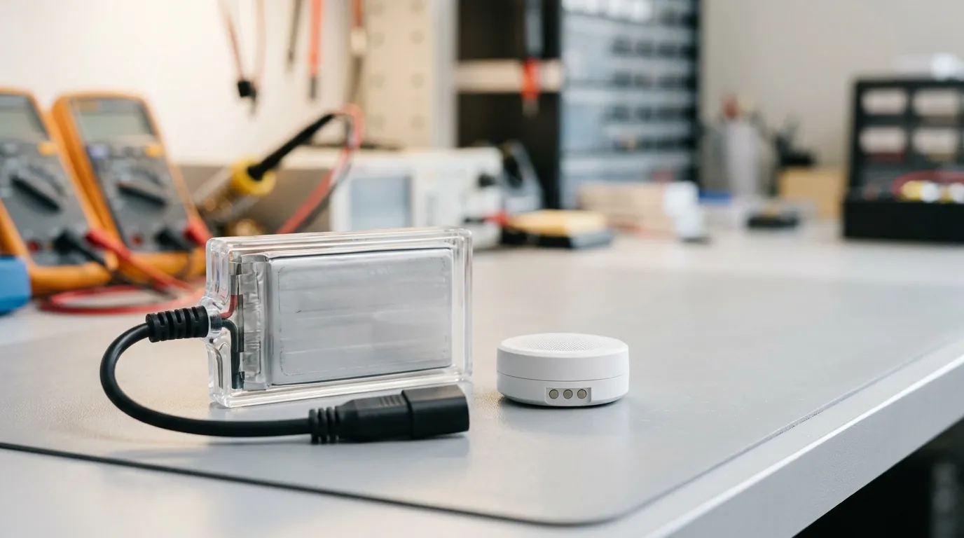
A rechargeable battery for a smart water-leak detector is an application-specific compact pack engineered to match the device's voltage, capacity, and peak-current demands while supporting sleep mode, periodic sensing, wireless transmissions, alarm events, recharging, and the environmental conditions of a moisture-prone installation site. Unlike a generic consumer battery, this pack must be specified around the detector's measured load profile, mechanical envelope, charging interface, and protection requirements — not chosen by capacity alone.
Smart water-leak detectors sit near sinks, water heaters, washing machines, and under cabinets, where they monitor for drips, flooding, and humidity changes. They must operate for months or years on a single charge while remaining small enough to fit unobtrusively in tight spaces. That combination of low average power, short high-current bursts, compact size, and exposure to humid or temperature-varying environments makes battery selection a design decision, not an afterthought.
This guide explains how to specify a rechargeable battery for a smart water-leak detector, including load profiling, chemistry trade-offs, electrical requirements, protection and charging, mechanical integration, validation, and supplier documentation.
Start with the Detector's Load Profile, Not the mAh Rating
The first mistake in battery selection is choosing a cell or pack by milliamp-hours (mAh) alone. A leak detector does not draw a constant current. It sleeps most of the time, wakes periodically to measure moisture or humidity, transmits short wireless packets, and may sound an audible alarm or send a push notification during a leak event. Each of these states draws a different current, and the battery must handle all of them.
Read the Current Profile Before Choosing Chemistry
Before selecting a battery chemistry, the device team should measure or estimate the detector's current draw in each operating state:
- Sleep current: the baseline current drawn by the microcontroller and sensor while the device is idle. This is often the dominant factor in long-term battery life.
- Sensing current: the additional current during a moisture or humidity measurement.
- Radio/transmission current: the short burst of current during Wi-Fi, Zigbee, Z-Wave, or Bluetooth transmission. This can be significantly higher than the sleep current.
- Alarm current: the current during an audible alarm, LED strobe, or extended transmission event.
The peak current — typically the radio burst or alarm event — determines the battery's required C-rate (the ratio of current to capacity) and affects whether the pack's protection circuit will trip. A battery with ample capacity but insufficient peak-current capability can experience voltage sag, causing the detector to brown out or reset precisely when it needs to report a leak.
The rated capacity in mAh only tells you how much charge the battery can store. It does not tell you whether the battery can deliver the current the device requires without excessive voltage drop.
Choosing Between Rechargeable AAA Cells and an Integrated Li-Ion or LiPo Pack

There are two practical rechargeable paths for a smart water-leak detector: use standard rechargeable AAA cells, or integrate a custom lithium-ion (Li-ion) or lithium-polymer (LiPo) pack.
Rechargeable AAA cells are a familiar consumer option. For example, IKEA's KLIPPBOK water-leak sensor lists two rechargeable HR03 AAA 1.2 V batteries as compatible, giving consumers a replaceable, standardized power source. From an OEM perspective, this approach simplifies battery sourcing and allows users to swap cells after several years of service. However, it constrains the device design: the battery compartment must fit standard AAA cells, the voltage platform is locked to the cell count and chemistry (for example, two Ni-MH cells in series provide a nominal 2.4 V), and the device needs a charging strategy — either an external charger or an integrated charging circuit.
An integrated Li-ion or LiPo pack offers more design freedom. A single Li-ion or LiPo cell typically provides a nominal voltage around 3.6 V to 3.7 V, which is close to the 3.3 V supply common in modern microcontrollers and sensors. The pack can be shaped to fit an unusual enclosure, specified with the right capacity and peak-current capability, paired with an appropriate protection circuit, and connected through a robust connector or direct soldering. The trade-off is that a custom pack requires a smaller-volume supplier, a defined charging solution, and sometimes additional documentation for transport or market access.
| Factor | Rechargeable AAA (Ni-MH) | Integrated Li-Ion/LiPo Pack |
|---|---|---|
| Nominal voltage per cell | 1.2 V | 3.6–3.7 V |
| Capacity | Depends on cell brand/type | Can be custom-sized to the device |
| Peak current | Limited by cell design | Can be specified for the device's radio/alarm burst |
| Replaceability | High — user can swap cells | Low — typically built-in or service-replaceable |
| Charging method | External charger or in-device | In-device charging circuit with CC/CV profile |
| Form factor | Constrained to AAA dimensions | Can be custom-shaped for the enclosure |
| Integration complexity | Low | Moderate — requires protection, connector, and validation |
| Documentation/transport | Lower risk (Ni-MH) | Lithium transport documents required |
For a device OEM, the choice depends on the product's positioning. A low-cost, consumer-replaceable sensor may favor rechargeable AAA cells. A sleek, sealed, or feature-rich detector — or one with a higher wireless duty cycle — may justify an integrated Li-ion or LiPo pack.
Electrical Requirements: Voltage, Capacity, Energy, and Current
Once the load profile is understood, the next step is to define the electrical requirements that will be sent to a battery supplier.
Nominal voltage. This is the rated midpoint voltage of the cell or pack during discharge. A single Li-ion or LiPo cell is commonly specified with a nominal voltage of 3.6 V or 3.7 V. The device's electronics must operate correctly across the pack's usable voltage range, which may drop below nominal during high-current bursts or as the battery depletes.
Maximum charge voltage. This is the upper voltage limit applied during charging. For a standard Li-ion or LiPo cell, this is often 4.2 V per cell. The charging circuit and the battery protection circuit must be matched to this limit. Do not confuse nominal voltage with maximum charge voltage — they serve different functions in the specification.
Capacity and energy. Capacity is stated in milliamp-hours (mAh) or ampere-hours (Ah) and describes the total charge the battery can store. Energy is stated in watt-hours (Wh) and accounts for the voltage: Wh = nominal voltage × capacity in Ah. When comparing packs of different voltages, Wh is the more meaningful figure because it reflects the actual energy available to the device.
Continuous and peak current. Continuous current is the sustained current the battery can deliver over an extended period. Peak current is the short-duration current the battery can support, often during a radio transmission or alarm event. The battery's protection circuit must be specified to allow the peak current without tripping, while still protecting against genuine overcurrent faults.
C-rate. The C-rate expresses current relative to capacity. A 1C rate means the discharge current equals the capacity in ampere-hours; for a 500 mAh pack, 1C equals 0.5 A. A 2C rate would be 1.0 A. The C-rate helps compare cells of different capacities and ensures the selected cell can support the device's peak load without excessive voltage sag.
Internal resistance. Every cell has internal resistance, which causes voltage to drop under load. A higher internal resistance translates to more voltage sag during a radio burst, which can trigger a low-voltage reset or cause the protection circuit to act prematurely. Lower internal resistance is generally better for burst-heavy devices.
Protection, Charging, and the Smart-Battery Question
A rechargeable lithium pack should not be connected directly to a device without protection. The protection circuit — often called a PCM (protection circuit module) or BMS (battery management system) depending on complexity — guards against overcharge, over-discharge, overcurrent, short-circuit, and in some designs, excessive temperature.
For a compact single-cell pack, a basic PCM may be sufficient. It monitors cell voltage and current, interrupts the circuit when a limit is exceeded, and resets when conditions return to normal. For packs with multiple cells in series, a more capable BMS is needed to manage cell balancing and protect each cell.
Smart BMS features — such as fuel gauging, state-of-charge estimation, and digital communication like SMBus, I2C, or Bluetooth — are optional. They add value when the device needs to display remaining battery percentage or report battery health to the user or a cloud platform. For a simple leak detector whose main job is to sound an alarm and send a notification, a basic protection circuit is often sufficient, though a fuel gauge can help the app tell the user when the battery is getting low.
Charging. A Li-ion or LiPo cell is charged using a constant-current, constant-voltage (CC/CV) profile. The charging circuit applies a constant current until the cell reaches its maximum charge voltage, then holds that voltage while the current tapers. The charger must be matched to the cell's chemistry, series count, capacity, and maximum recommended charge current. Charging too quickly or above the recommended voltage can degrade the cell or create a safety risk. The device design must also accommodate charging temperature limits — lithium cells typically should not be charged below 0 °C.
Mechanical and Environmental Fit: Enclosure, Connector, Temperature, and Moisture
Battery selection is not only electrical. The pack must fit inside the detector's enclosure without being compressed, punctured, or subjected to sharp edges. The connector must be rated for the device's current, keyed to prevent reverse polarity, and robust enough to survive assembly and field handling. Wire gauge must match the peak current without excessive resistance.
Temperature is a second major constraint. A leak detector installed near a hot water pipe may see elevated temperatures; one in an unheated crawl space may approach freezing. The battery's discharge temperature range must cover the device's operating environment, and its charge temperature range must match the conditions under which the device is recharged. Storage temperature also matters: a detector that sits in warehouse inventory for months should not be stored at a high state of charge in extreme heat.
Finally, moisture exposure must be handled at the system level. An IP rating applies to the complete product or a tested enclosure, not to the battery cell itself. For example, the X-Sense SWS51 smart water-leak detector lists an IP66 rating for the device, but that rating does not imply the battery inside is waterproof. The enclosure design, sealing, and any potting or conformal coating around the battery compartment determine the product's moisture resistance.
Validating the Prototype Before Mass Production
A datasheet is a starting point, not a guarantee. Before approving a pack for mass production, the prototype should be validated under conditions that match the real device.
Test the prototype with the final load profile: the same sleep current, sensing interval, radio transmit duration, and alarm current. Measure the pack voltage during the worst-case burst to confirm there is no disruptive voltage sag. Run the prototype through repeated charge/discharge cycles to confirm cycle life and capacity retention under expected conditions. Test at the temperature extremes the device is likely to see in the field. And test with the final charger, connector, and enclosure so the interaction between the pack and the rest of the system is captured.
Document the results against the specifications. A pack that looks good on paper but sags under a radio burst, trips the protection circuit, or fails to reach the rated cycle life in the actual device is not fit for production.
Documentation and Compliance: What to Request from a Lithium-Battery Supplier
When sourcing a custom lithium pack, the supplier should be able to provide certain documents. These documents protect the OEM, support market access, and help the product move across borders.
- Model-specific datasheet or technical data sheet (TDS): describes voltage, capacity, current, dimensions, temperature range, protection features, and other specifications for the exact model being supplied.
- SDS/MSDS (Safety Data Sheet / Material Safety Data Sheet): documents the material hazards and handling guidance for the battery or its contents, where applicable.
- UN 38.3 test summary: required for lithium cells and batteries shipped by air, sea, or road. UN 38.3 is the UN testing standard for lithium battery transport safety, covering tests such as altitude simulation, thermal cycling, vibration, shock, external short circuit, impact, overcharge, and forced discharge. The test summary must relate to the specific cell or battery model being shipped.
- IEC/UL/CB safety test report: product-level safety testing tied to a defined model and construction. This is not a company-wide certification; it applies to the specific model tested.
- Market declarations such as CE, RoHS, or REACH: apply depending on the destination market and should be confirmed before shipment.
Product certification is not the same as company quality-system certification. A company may hold ISO 9001 for its manufacturing processes, but that does not certify a specific battery model. The OEM should verify that each document matches the exact model, standard edition, test conditions, and scope before relying on it.
The United Nations Manual of Tests and Criteria provides the framework for the UN 38.3 transport testing and documentation of lithium batteries.
Submitting the Battery RFQ: What the Manufacturer Needs to Know

A useful battery quotation depends on a complete request. When contacting a battery manufacturer such as Gloflux, provide the following information:
- Device current profile: sleep current, sensing current, radio transmit current and duration, and alarm current.
- Voltage platform: nominal voltage and acceptable operating range.
- Capacity/energy target: target mAh or Wh and the expected runtime under the load profile.
- Maximum dimensions and form factor: available space inside the enclosure, including any constraints on thickness or shape.
- Connector and wiring requirements: connector type, pinout, polarity keying, and wire length or gauge if specified.
- Operating and storage temperature range: include charging temperature if the device charges in place.
- Charging method: whether the device charges via USB, a dedicated charger, or another interface, and the expected charge current.
- Target cycle life: the number of charge/discharge cycles expected and the capacity retention threshold.
- Target market and documentation requirements: destination markets, transport methods, and any certifications or declarations required.
- Production volume and timeline: expected annual volume, prototype timing, and mass-production launch date.
These inputs allow the manufacturer to propose a cell, protection circuit, connector, and enclosure design that fits the product — rather than a generic off-the-shelf battery that may not survive the device's real operating conditions.
Smart Home Battery Solutions from Gloflux
Gloflux, a lithium battery manufacturer and OEM/ODM partner, offers battery solutions for smart home applications. Its smart home battery page lists a range of options, including LiPo batteries, high-capacity Li-ion batteries, custom-shaped batteries, and low-self-discharge batteries — the types of solutions that can be tuned for compact connected devices like smart leak detectors.
As with any custom battery project, the correct approach is not to pick a cell from a catalog but to define the device's requirements, validate a prototype, and work with the manufacturer to finalize the pack architecture, protection, charging, and documentation.
Rechargeable Battery for Smart Leak Detectors: A Summary of Key Specifications
| Parameter | Typical Considerations for a Smart Water-Leak Detector |
|---|---|
| Nominal voltage | Single-cell Li-ion/LiPo: ~3.6–3.7 V; two Ni-MH AAA: ~2.4 V |
| Maximum charge voltage | Li-ion/LiPo: ~4.2 V (depending on the cell); Ni-MH: charging method-specific |
| Capacity (mAh/Ah) | Determined by sleep current and target runtime |
| Energy (Wh) | Nominal voltage × capacity in Ah |
| Continuous current | Set by the sustained sensing and radio operation |
| Peak/radio/alarm current | Must be supported without voltage sag or protection trips |
| C-rate requirement | Peak current ÷ capacity (in Ah) |
| Protection | PCM or BMS: overcharge, over-discharge, overcurrent, short-circuit, temperature |
| Charging method | CC/CV for Li-ion/LiPo; must match chemistry and series count |
| Connector | Keyed for polarity, rated for peak current |
| Enclosure | No compression or sharp edges; thermal path considered |
| IP rating | Applies to the complete device, not the battery alone |
| Operating temperature | Discharge and charging limits must match installation environment |
| Storage temperature | Consider warehouse and shelf-life conditions |
| Documentation | Datasheet/TDS, UN38.3 test summary, model-specific safety report, market declarations |
Related Smart Home Battery Applications
When selecting a rechargeable battery for a smart water-leak detector, it helps to consider how the same engineering principles apply to other compact smart home devices. A lithium battery for smart lock must support low standby power and burst current during motor operation, while a Lithium battery for smart thermostats must handle similar wireless communication and sensing loads in an environmentally exposed location. For a broader view of powering connected sensing products, the rechargeable battery for iot sensors guide covers a wider range of low-power IoT applications.
Even when a compact sensor seems like a good fit for a standard cylindrical cell, always verify the mechanical envelope first. For example, a 7 4v 2600mah 18650 battery pack offers substantial capacity, but its cylindrical form factor is often too bulky for a slim leak-detector enclosure. The RFQ checklist above helps you avoid specifying a pack that cannot physically fit the product.
Need Help Sizing a Rechargeable Battery for Your Smart Leak Detector?
If you are designing a smart water-leak detector and need help selecting or customizing a compact rechargeable battery pack, contact the Gloflux team with your device's current profile, mechanical envelope, and target market requirements. A custom battery design can be developed around your load profile, charging method, and environmental conditions — rather than forcing your product around an off-the-shelf cell.
Talk to the Manufacturer
Resources & Insights

High Capacity Lithium Battery for Wearables: High-Voltage LiPo Cell Design
2026-10-19

Cylindrical Battery Packs for Laptops: 2S vs 3S vs 4S Battery Design
2026-10-19

Stage Lighting Battery Pack: Prevent Voltage Drop & LED Flicker
2026-10-19

Best Rechargeable Batteries for Smart Devices: Performance, Safety, and Selection Guide
2026-10-19


