


 Home /
 Lithium Battery for Satellite Equipment: Custom Pack Design Considerations


Table of Contents
- Why Satellite Equipment Needs a Custom Battery Pack
- Electrical Design: Voltage, Capacity, Energy, Current, and C-Rate
- Cell Chemistry and Format Selection: Li-ion vs Li-Polymer
- Pack Architecture: Series, Parallel, and BMS
- Verification, Qualification, and Documentation
- What to Send a Battery Supplier Before Requesting a Quote
- Summary: Design, Verify, Document, and Purchase
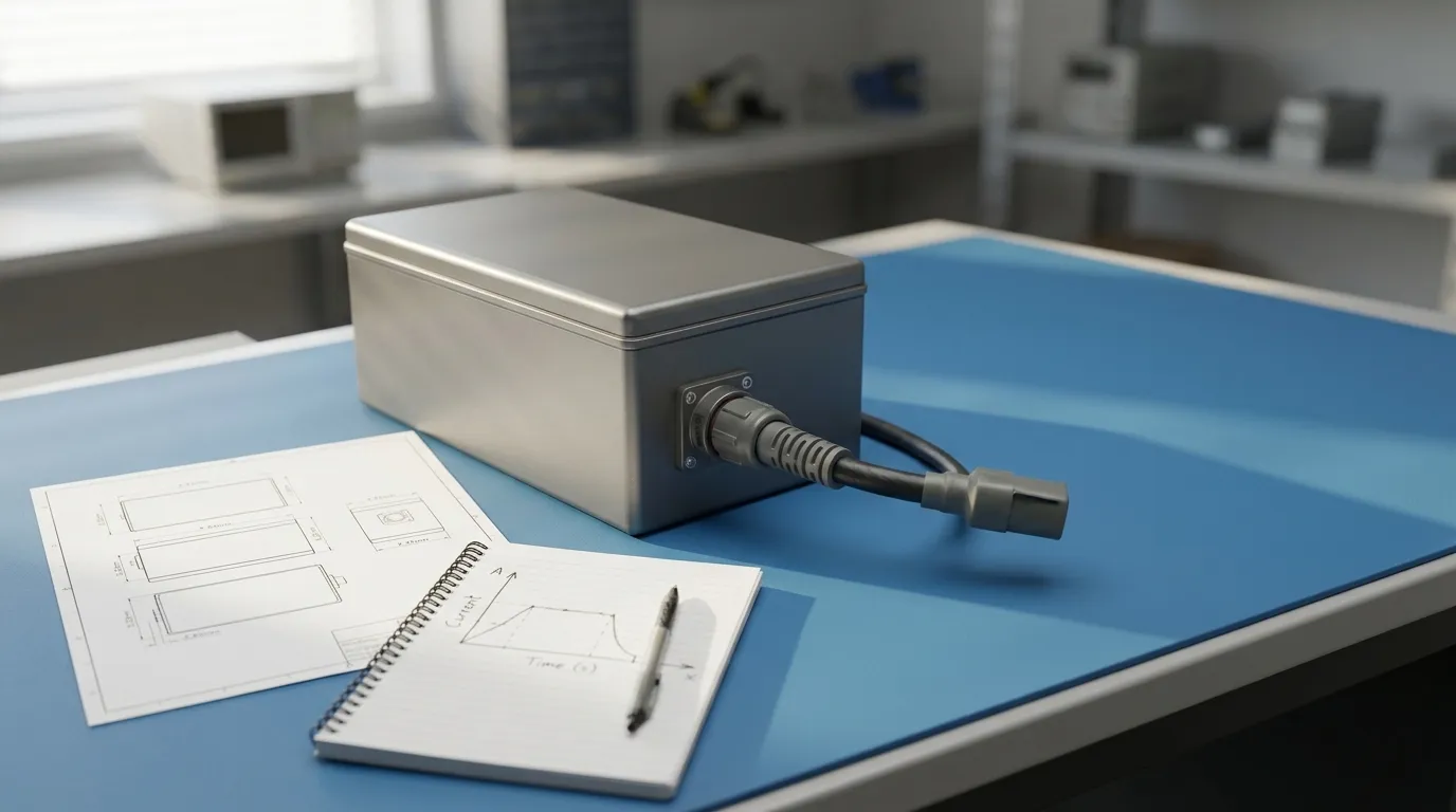
A lithium battery for satellite equipment is a mission-specific battery assembly that must be engineered from the equipment's load profile, end-of-life energy needs, charging architecture, and mechanical and thermal environment—not selected as a standard off-the-shelf pack. This guide explains how to translate satellite-equipment requirements into a custom battery-pack specification, what design decisions matter, and what documentation you should require from a battery supplier.
Satellite equipment spans spacecraft subsystems and ground-based test systems, each with different power demands and environmental constraints. The design process described here applies to custom battery packs for satellite hardware, including communication subsystems, avionics, sensors, and test equipment.
Why Satellite Equipment Needs a Custom Battery Pack
Commercial lithium battery packs are designed for controlled environments. Satellite equipment operates under conditions that challenge standard battery designs: wide temperature swings, vacuum exposure, launch vibration, and mission profiles that may require specific charge/discharge cycles over years of operation.
A custom pack lets you match the battery to the actual load. Satellite subsystems rarely draw a constant current. Communication equipment may idle for long periods, then draw a high pulse during transmission. Sensors and heaters add intermittent loads. A standard pack may fail during peak demand or be unnecessarily heavy for the mission.
The table below summarizes how satellite-equipment environments influence battery design:
| Environment or Requirement | Design Implication |
|---|---|
| Wide temperature range | Cell chemistry selection, thermal management, and charge limits |
| Vacuum exposure | Materials selection, outgassing control, thermal path design |
| Launch vibration and shock | Mechanical restraint, cell mounting, connector locking |
| Long mission duration | End-of-life capacity margin, cycle life, and reliability |
| Intermittent high-current pulses | Cell current capability, pack impedance, BMS current limits |
| Charging architecture | Charge voltage, charge current, and charge-control compatibility |
Satellite Equipment Versus Aerospace Test Equipment
It is worth distinguishing satellite flight hardware from aerospace test equipment. Test equipment often operates in a controlled laboratory or ground environment where temperature, pressure, and mechanical loads are less extreme. A Rechargeable battery for aerospace test equipment may not need the same vacuum, radiation, or launch-load qualification as an orbital battery. The documentation burden is also different: flight hardware generally requires more rigorous traceability and verification evidence. Keep this boundary in mind when specifying your battery.
Electrical Design: Voltage, Capacity, Energy, Current, and C-Rate
The first step in designing a custom satellite-equipment battery is defining the electrical requirements. Four values matter most: nominal voltage, capacity, energy, and current capability.
Nominal voltage is the pack's rated operating voltage, determined by the number of cells connected in series. Each lithium-ion cell has a nominal voltage around 3.6–3.7 V, depending on chemistry. A 4S configuration (four cells in series) produces a nominal pack voltage of about 14.4–14.8 V.
Maximum charge voltage is higher than nominal. A typical lithium-ion cell charges to 4.2 V, so a 4S pack charges to about 16.8 V. Your equipment and charger must tolerate this upper voltage.
Capacity, measured in ampere-hours (Ah), describes how much charge the pack can store. Energy, measured in watt-hours (Wh), is the more useful value for mission planning because it accounts for voltage. The relationship is simple:
Energy (Wh) = Nominal Voltage (V) × Capacity (Ah)
A 14.8 V pack with 10 Ah capacity stores 148 Wh of energy. If the equipment draws 14.8 W on average, the pack could theoretically run for 10 hours—before accounting for losses, temperature effects, and end-of-life degradation.
End-of-life (EOL) margin is critical for satellite equipment. Battery capacity fades with cycling and age. A pack sized to meet requirements on day one may fall short after two years of operation. A common approach is to size the pack so that its capacity at end of mission, not beginning of life, meets the load requirement.
Continuous current is the steady current the pack must deliver. Peak current is the short-duration current during transmission, motor startup, or heater activation. C-rate normalizes current relative to capacity. A 10 Ah pack delivering 20 A is operating at 2C. A pack that can deliver high C-rates needs cells with low internal resistance and a BMS designed for high current.
Calculating a First-Pass Pack Size from a Load Profile
A simple worked example shows the process. Assume a satellite communication subsystem requires:
- 14.4 V nominal operating voltage
- 2 A average continuous current
- 8 A peak current for 2 minutes during each transmission cycle
- 3 hours of operation per orbit, repeated daily
- 2-year mission with 30% capacity fade at end of life
Step 1: Calculate daily energy consumption.
Average current: 2 A × 14.4 V = 28.8 W
Daily energy: 28.8 W × 3 hours = 86.4 Wh
Step 2: Add end-of-life margin.
If the pack retains 70% of initial capacity at end of life, initial energy must be higher:
86.4 Wh ÷ 0.70 = 123.4 Wh minimum initial energy
Step 3: Convert to capacity.
123.4 Wh ÷ 14.4 V ≈ 8.6 Ah
Step 4: Check peak current against cell capability.
Peak current is 8 A. For a 9 Ah pack, that is a modest 0.9C rate. Most lithium-ion cells handle this easily. If the load were 40 A on the same pack, the C-rate would be 4.4C, requiring cells specifically rated for high-rate discharge and a BMS configured for that current.
This is a simplified first pass. Real satellite battery design also considers depth of discharge per cycle, charge time, temperature, and the specific charge profile. But the method shows why sizing starts with the load profile—not with the biggest battery available.
Cell Chemistry and Format Selection: Li-ion vs Li-Polymer

The next decision is cell chemistry and format. Two common options are lithium-ion cylindrical cells and lithium-polymer (LiPo) pouch cells.
Lithium-ion cylindrical cells (such as 18650 or 21700 formats) are widely used in industrial and aerospace applications. They offer mature manufacturing, good energy density, and predictable mechanical behaviour. Cylindrical cells are relatively easy to mount, interconnect, and cool. Their rigid steel cans provide mechanical protection and resist swelling.
Lithium-polymer (LiPo) pouch cells use a flexible aluminium-laminated pouch. They can be manufactured in custom shapes and are often lighter for a given footprint. LiPo cells can deliver high discharge currents, which is a key reason they are widely used in high-power portable applications—though that same high-rate capability, as seen in a lipo battery for drone application, also requires careful thermal design. LiPo cells require careful mechanical restraint to control swelling over life, and their soft casing is more vulnerable to puncture. Thermal management and cell spacing need more design attention.
| Factor | Cylindrical Li-ion | Li-Polymer (LiPo) |
|---|---|---|
| Form factor | Rigid cylinder | Flexible pouch |
| Mechanical protection | Built-in can | Requires external restraint |
| Energy density | High | High (varies by cell) |
| Shape flexibility | Limited | High |
| Swelling behaviour | Minimal | Must be managed |
| Thermal management | Relatively straightforward | Requires careful cell spacing |
| Current capability | Cell-dependent | Cell-dependent |
Neither format is universally superior. The right choice depends on your available space, mechanical design, current requirements, and thermal environment. The table should make clear that cell selection is a trade-off, not a default.
Pack Architecture: Series, Parallel, and BMS
Once cells are selected, the pack architecture determines voltage, capacity, and current capability.
Series connections add cell voltages. Four 3.7 V cells in series produce 14.8 V nominal. Parallel connections add capacity. Two 5 Ah cells in parallel produce 10 Ah at the same voltage.
A full pack description includes both: "4S2P" means four series strings, each with two cells in parallel, producing a pack with the voltage of four cells and the capacity of two cells.
| Configuration | Nominal Voltage | Capacity Example | Notes |
|---|---|---|---|
| 1S1P | 3.7 V | 5 Ah | Single cell |
| 4S1P | 14.8 V | 5 Ah | Voltage multiplied, capacity unchanged |
| 4S2P | 14.8 V | 10 Ah | Voltage and capacity both increased |
| 4S4P | 14.8 V | 20 Ah | Higher capacity and current capability |
Parallel cells share the load, so a higher P count can also increase available current—provided the cells are well matched and the BMS can manage the architecture.
BMS and Protection
A battery management system (BMS) or a simpler protection circuit module (PCM) monitors the pack and protects against unsafe conditions. The difference matters:
- A PCM typically provides basic protection against overcharge, over-discharge, overcurrent, and short circuit. It may not provide cell balancing or communication.
- A BMS can add cell balancing, state-of-charge estimation, state-of-health reporting, temperature monitoring, and communication interfaces such as SMBus, I2C, UART, CAN, RS485, or Bluetooth. Not every BMS supports every protocol—the feature set depends on the specific BMS design.
For satellite equipment, the BMS requirements depend on whether the host system needs to know battery status. If the equipment monitors its own power source, a smart BMS with a fuel gauge and telemetry may be required. If the battery operates independently with fixed charge/discharge limits, a well-configured PCM may be sufficient.
Whatever protection is used, the BMS or PCM thresholds must match the cell chemistry, series count, and application. A BMS configured for one pack cannot be assumed to work on another.
Charging Requirements
The charger must match the pack's chemistry, series count, and charge voltage. A 4S Li-ion pack charges to about 16.8 V. Charging methods commonly use constant current followed by constant voltage (CC/CV), with a recommended charge current based on the cells' datasheet.
Charging in space presents additional challenges. In orbit, the battery may be charged from solar panels with a variable input. On the ground, it may be charged from a bench supply. The charging architecture must be defined early because it affects BMS design, connector selection, and cell selection.
Mechanical and Thermal Integration
Mechanical and thermal design are as important as electrical selection for satellite equipment.
Enclosure design. The pack enclosure protects cells from mechanical damage, provides mounting points, and constrains cell movement during launch vibration. The enclosure material must be compatible with vacuum operation—some materials release volatile compounds (outgassing) that can contaminate sensitive optics or electronics.
Thermal management. Lithium-ion cells perform best within a defined temperature range. In vacuum, heat cannot escape by convection, so the pack must conduct heat to a radiator or spacecraft structure. Cells operating too hot degrade faster; cells operating too cold may not accept charge effectively. The thermal path between cells, the enclosure, and the mounting surface is a deliberate design element, not an afterthought.
Connector and wiring. The connector must match the current requirement and the mechanical interface. A high-current peak load requires appropriately sized wiring and a connector rated for that current. Polarity, locking mechanism, and vibration resistance are all part of the specification.
Ingress protection. If the battery is used in ground test equipment, an IP rating might matter. If it is sealed inside a spacecraft compartment, IP ratings may be irrelevant. Do not assume IP protection is needed—or that an IP rating from one product applies to another.
Verification, Qualification, and Documentation
The difference between a commercial pack and a satellite-equipment pack is often the documentation. What evidence should you expect from a supplier?
UN38.3 transport testing. Lithium batteries are regulated for transport. UN38.3 testing verifies that a specific battery design passes a series of tests—altitude simulation, thermal cycling, vibration, shock, external short circuit, impact, overcharge, and forced discharge—for safe transport. A UN38.3 test summary is transport documentation. It is not space qualification.
IEC/UL product safety testing. IEC 62133 and UL standards address the safety of portable sealed secondary cells and battery packs. A product-level report applies to a defined model, construction, and standard scope. It cannot be generalized to other packs.
Space-specific standards. ISO 17546:2024, Space systems — Lithium ion battery for space vehicles, specifies design and minimum verification requirements for lithium-ion batteries used in space, covering performance, safety, and logistics. NASA also publishes extensive guidance on battery use in space applications. These documents are useful references when defining your own verification plan.
Prototype versus qualification versus production. The evidence you need depends on the development stage. A prototype demonstrates feasibility. A qualification unit is tested to prove the design meets requirements. Production units follow a controlled manufacturing process. Ask which stage produced the test data you are being shown.
Traceability and change control. Mission-critical batteries need cell traceability. If a cell batch changes, the pack's performance may change. A qualified supplier should have change control processes that notify you before substituting cells, BMS components, or manufacturing processes. For custom packs, this is not optional.
| Documentation | What It Proves | What It Does Not Prove |
|---|---|---|
| UN38.3 test summary | Safe transport of a specific battery design | Space qualification, long-term reliability |
| IEC/UL report | Product safety for a defined model/construction | Performance in orbit, radiation tolerance |
| Cell datasheet | Cell-level electrical and environmental limits | Pack-level performance |
| Pack test report | Pack-level performance under stated conditions | Performance under unspecified conditions |
| Qualification report | Design meets specified requirements | Production consistency over time |
| Traceability records | Batch and component history | Future change control |
What to Send a Battery Supplier Before Requesting a Quote

A battery supplier can only design the right pack if you provide the right information. Before requesting a quote, prepare the following:
Electrical requirements
- Nominal voltage and acceptable voltage range
- Maximum charge voltage and charge method
- Average continuous current and peak current (with duration)
- Capacity or energy requirement (Ah or Wh)
- End-of-life capacity margin
- Charge/discharge cycle profile
Mechanical requirements
- Available space (length, width, height)
- Maximum weight
- Mounting method and connector preferences
- Vibration and shock environment
Thermal requirements
- Operating temperature range (charge and discharge)
- Storage temperature range
- Heat dissipation path and available cooling
Environmental requirements
- Vacuum exposure (yes/no)
- Radiation environment (if known)
- Pressure or humidity conditions
Mission requirements
- Mission duration
- Expected number of charge/discharge cycles
- Depth of discharge per cycle
- Whether the battery is a prototype, qualification unit, or production unit
Documentation requirements
- Datasheet/TDS
- SDS/MSDS
- UN38.3 test summary
- Test reports (cell-level and pack-level)
- Traceability and change control policy
Providing this information upfront helps the supplier avoid guesswork and gives you a more accurate proposal. It also shows the supplier you understand the design process.
Summary: Design, Verify, Document, and Purchase
A custom lithium battery for satellite equipment is designed in four stages:
- Define the requirements. Capture the load profile, voltage, energy, current, temperature, mechanical, and mission requirements.
- Design the pack. Select chemistry, cell format, S/P configuration, BMS, connector, and enclosure.
- Verify the design. Test prototypes, qualification units, and production units against the specification.
- Document everything. Require datasheets, test reports, transport documentation, traceability, and change control.
Whether you are designing a ground-support battery or comparing high-rate pack options, it helps to work with a drone battery manufacturer that understands high-current demand, or an fpv drone battery manufacturer experienced with aggressive discharge profiles—but satellite hardware demands a different level of verification and documentation.
Gloflux provides custom battery pack design and OEM/ODM manufacturing for industrial and application-specific equipment. If you are specifying a lithium battery for satellite equipment, start by documenting your load profile and design constraints, then submit those requirements for a technical review.
Talk to the Manufacturer
Resources & Insights

High Capacity Lithium Battery for Wearables: High-Voltage LiPo Cell Design
2026-10-19

Cylindrical Battery Packs for Laptops: 2S vs 3S vs 4S Battery Design
2026-10-19

Stage Lighting Battery Pack: Prevent Voltage Drop & LED Flicker
2026-10-19

Best Rechargeable Batteries for Smart Devices: Performance, Safety, and Selection Guide
2026-10-19


