


 Home /
 Custom Battery Pack Connector Selection Guide for OEM Designs


Table of Contents
- What to Know Before You Choose a Battery-Pack Connector
-
Step-by-Step Connector Selection Process
- Step 1 — Define the Electrical Interface
- Step 2 — Define the Mechanical Interface
- Step 3 — Plan the Power, Signal, and Communication Contacts
- Step 4 — Assess the Environment and Operating Conditions
- Step 5 — Confirm the Mating Half, Polarity, and Keying
- Step 6 — Choose Standard or Custom Harness
- Step 7 — Verify the Complete Current Path
- Step 8 — Validate with a Prototype Sample
- How to Specify the Connector in an OEM RFQ
- Common Connector Mistakes and How to Avoid Them
- Conclusion and Supplier Review Checklist
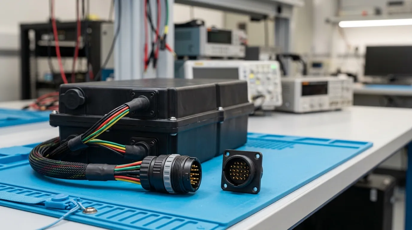
Selecting the right connector for a custom battery pack means mapping the device's electrical load, mechanical constraints, environmental conditions, and signal requirements to a connector and wiring specification, then validating that choice in a prototype before mass production. The connector is not an afterthought — it is part of the pack's electrical path, and its rating, together with the wire, terminal, and PCB trace ratings, must each support the actual current the device will draw.
For OEMs developing custom lithium battery packs, the connector decision sits at the intersection of electrical engineering, mechanical design, and manufacturing reliability. Getting it wrong can mean voltage drop under load, intermittent disconnects, overheating, or field failures that are difficult to trace. The good news is that connector selection follows a repeatable process — one that turns vague requirements into a specification a battery supplier can implement without guesswork.
What to Know Before You Choose a Battery-Pack Connector
A battery-pack connector is the physical and electrical interface between the battery pack and the device it powers. It includes the contacts that carry current, the housing that holds them, any locking or retention features, strain relief for the cable, and the mating half inside the device.
The connector is part of a complete current path: cell → busbar or nickel strip → wire → terminal → connector contact → device-side receptacle → PCB trace. Every element in that path must be rated for the current it will carry. A connector rated for 10 A does no good if the attached wire is only rated for 5 A, or if the terminal crimp is poor enough to create a high-resistance joint that heats up under load.
Several common confusions affect connector selection:
- Cell vs. pack vs. connector rating. The cell's discharge capability and the pack's rated current do not automatically determine what the connector must handle. The connector must be sized for the actual current path in the device, not for the pack's theoretical maximum.
- Nominal voltage vs. maximum charge voltage. Connector voltage ratings must be checked against the pack's maximum charge voltage, not its nominal voltage. For example, a "3.7 V" Li-ion pack charges to 4.2 V per series group, and the connector and insulation must tolerate that.
- Amps vs. C-rate. Connector selection is done in amperes, not C-rate. A 2C discharge from a 5 Ah pack is 10 A; from a 20 Ah pack it is 40 A. The connector only cares about the amperes.
- Capacity vs. energy. Capacity (mAh or Ah) describes charge; energy (Wh) describes total work capacity. Neither directly gives you the connector current — you need the device's actual load profile.
Step-by-Step Connector Selection Process
The connector should be chosen only after the load, voltage, space, environment, and signal requirements are known. A connector that meets a catalogue rating but not the measured current path is still the wrong connector.
- Define the electrical interface — voltage, continuous current, peak current, and duty cycle.
- Define the mechanical interface — space, orientation, locking, strain relief, and mating cycles.
- Plan the power, signal, and communication contacts — main current, NTC, balance, fuel gauge, and communication lines.
- Assess the environment and operating conditions — temperature, moisture, dust, vibration, shock, and chemical exposure.
- Confirm the mating half, polarity, and keying — the connector must mate correctly and only one way.
- Choose standard or custom harness — decide whether a catalogue connector works or a custom assembly is required.
- Verify the complete current path — connector, wire, terminal, and PCB trace together.
- Validate with a prototype sample — prove the connector works in the actual device.
Step 1 — Define the Electrical Interface
The electrical requirement starts with the device's load profile, not the battery's capacity.
Continuous current is the sustained load during normal operation, expressed in amperes. A medical device that draws 2 A continuously needs a connector capable of carrying 2 A indefinitely without excessive temperature rise.
Peak current is the transient load — motor startup, radio transmission, or inrush current — that may last only milliseconds or seconds. A robot that draws 3 A normally but 12 A during acceleration needs a connector that can handle the peak without voltage sag or contact damage.
Duty cycle matters because connector heating depends on both current magnitude and duration. A 15 A peak that occurs for 50 ms every minute is very different from a 15 A peak that occurs for 30 seconds every minute. The connector, wire, and terminal must all be evaluated for the worst realistic duty cycle.
Voltage rating should be checked against the pack's maximum charge voltage — not its nominal voltage. The connector's insulation and contact spacing must tolerate the highest voltage present in the system, including during charging.
Specify in amperes, not C-rate. If the pack is 10 Ah and the device draws 2C, the connector must carry 20 A. State the amperage directly in the specification.
Step 2 — Define the Mechanical Interface
The mechanical environment determines whether a standard wire-to-board or wire-to-wire connector works, or whether a custom harness is necessary.
Available space inside the device limits connector size. A compact wearable may only fit a low-profile connector with a small pitch, while an industrial robot may have room for a larger, more robust connector.
Orientation and mating direction matter. A connector that must be plugged into a board perpendicular to the pack surface needs a different housing design than one that mates parallel to it. The connector and its mating half must be specified together — they are a matched pair.
Locking and retention prevent accidental disconnects under vibration or handling. A friction-fit connector is easy to unplug but may work loose. A latch or locking connector requires a deliberate action to disconnect, which is preferable in high-vibration applications.
Strain relief protects the wire-to-terminal joint from cable pull and repeated flexing. A connector without strain relief is a reliability risk, especially when the cable exits the pack at an angle or moves during device operation.
Pitch refers to the spacing between contacts. A smaller pitch allows more contacts in less space but may reduce current capacity and make crimping more demanding.
Mating cycles matter for replaceable or removable packs. A battery that is swapped daily over a three-year product life needs a connector rated for hundreds or thousands of mating cycles, not a connector designed for one-time installation.
Step 3 — Plan the Power, Signal, and Communication Contacts
A battery-pack connector is often more than a power connector. It may carry sensing, communication, and balance lines in the same housing.
Power contacts carry the main discharge current. These are the largest contacts in the connector and are sized for the continuous and peak current defined in Step 1.
NTC thermistor contacts carry temperature-sensing signals from a thermistor mounted on or inside the pack. The device or the BMS uses this signal to monitor pack temperature during charge and discharge. For deeper guidance on thermistor placement and wiring, see our guide on NTC thermistor for lithium battery packs.
Balance contacts may be necessary in multi-series packs where individual cell groups need voltage monitoring or balancing. These are low-current signal lines.
Fuel gauge contacts carry state-of-charge data from a fuel-gauge IC to the device, allowing the device to display remaining runtime.
Communication contacts support protocols such as SMBus, I²C, CAN, UART, RS485, or Bluetooth. Gloflux's customization page lists SMBus, I²C, and CAN as optional communication protocols for custom battery packs. The architecture of the protection and communication system is explained in more detail in our guide to custom battery bms design. The choice of protocol affects the pin count and pinout of the connector.
Pinout must be defined before the connector is selected. A connector with the right current rating but the wrong pinout is a functional failure. The pinout drawing should be part of the connector specification, reviewed by both the device design team and the battery supplier.
Step 4 — Assess the Environment and Operating Conditions
The connector must survive the environment the device operates in — not just the environment of the engineering lab.
Temperature affects contact resistance, housing material, and wire insulation. A connector rated for indoor consumer use may not be suitable for outdoor equipment exposed to freezing winters or direct sunlight. The connector's operating temperature range must be checked against both the ambient temperature and the self-heating caused by current flow.
Moisture and dust can corrode contacts or create conductive paths between pins. An IP rating — defined by IEC standards — describes the level of ingress protection, but it must be documented for the specific connector or enclosure. "Water-resistant" or "waterproof" language without an IP classification is not a specification.
Vibration and shock are critical for robotics, AGVs, outdoor equipment, and any device that moves or is transported. A connector that passes a bench test may fail after weeks of vibration if the locking mechanism is inadequate.
Chemical exposure matters for medical, industrial, or outdoor devices that may come into contact with cleaning agents, fuels, or other chemicals.
Step 5 — Confirm the Mating Half, Polarity, and Keying
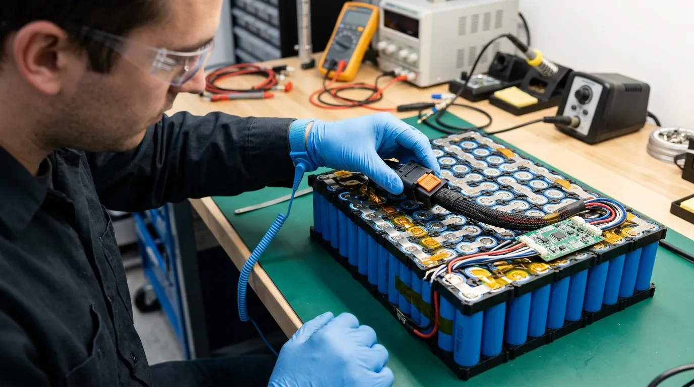
The connector is only as good as its mating half. The device-side receptacle must be specified from the same connector manufacturer's catalogue as the pack-side connector — mixing brands or series can create fit and electrical problems.
Polarity and keying are physical features that prevent incorrect mating. A keyed connector can only be inserted one way. This is especially important for packs where reverse polarity could damage the device or create a safety hazard.
Pinout verification is a design review step, not a manufacturing step. The pinout must be checked against the device schematic before the connector is finalized. A reversed power connection or a misrouted communication line is a design error that no amount of manufacturing quality control can catch.
Redundant locking may be appropriate for high-vibration applications. A primary latch plus a secondary retention feature provides extra protection against accidental disconnects.
Step 6 — Choose Standard or Custom Harness
A standard connector is a catalogue part with published electrical, mechanical, and environmental specifications. It is faster to source, has a proven track record, and its mating half is readily available. Standard connectors are the right choice when a catalogue product meets the requirements.
A custom harness is necessary when the device's packaging, routing, wire length, terminal type, or branching requirements differ from any standard product. Customization may include:
- Wire length tailored to the device layout.
- Terminal type matched to the connector or mating half.
- Branching method for multiple outputs.
- Enclosure integration or specialized strain relief.
Gloflux states on its customization page that wiring length, terminal type, and branching method can be customized as part of its battery-pack development service. This means the connector does not have to be a compromise — it can be built to match the device.
Step 7 — Verify the Complete Current Path
A connector can be individually rated yet fail in the assembled device because the wire, terminal, or enclosure was undersized, mismated, or not validated together.
The current path includes:
- The connector contact.
- The wire gauge.
- The terminal crimp.
- The PCB trace on the device side.
- The mating half's contact resistance.
If any element in this path is undersized, it becomes the limiting factor. A 10 A connector with a 22 AWG wire rated for 7 A is a 7 A circuit, regardless of the connector's rating.
Contact resistance and poor crimping are the most common causes of connector heating. A high-resistance crimp creates localized heat under load, which can melt wire insulation, discolor the housing, or eventually cause an open circuit. Voltage drop under load — sometimes mistaken for a battery problem — is often a connector, wire, or harness issue.
Step 8 — Validate with a Prototype Sample
A prototype sample is the final proof that the connector works in the real device. The sample must be tested with:
- The actual device-side mating half.
- The specified wire gauge and terminal.
- The final enclosure or strain-relief arrangement.
- The real electrical load profile.
Validation should cover fit, pinout, polarity, locking, strain relief, current path, and temperature behavior. Vibration, shock, temperature, and moisture are best evaluated in the device, not inferred from a datasheet. The production testing and inspection methods used to confirm connector quality are covered in our guide to lithium battery quality control and testing.
The OEM must approve the sample before mass production begins. This approval is the point where the connector specification becomes a production commitment.
How to Specify the Connector in an OEM RFQ

When you send a battery-pack connector requirement to a supplier, the RFQ must be complete enough that the supplier can implement it without guesswork. A good RFQ states requirements, not preferences.
Electrical requirements:
- Maximum system voltage (use maximum charge voltage, not nominal).
- Continuous current.
- Peak current and duration.
- Duty cycle.
- Acceptable voltage drop (if constrained by device performance).
Mechanical requirements:
- Available space (length, width, height).
- Mating orientation.
- Locking and retention requirements.
- Strain relief requirements.
- Wire length and routing.
- Expected mating cycles.
Signal requirements:
- NTC thermistor pins.
- Balance pins.
- Fuel gauge pins.
- Communication protocol and pinout (SMBus, I²C, CAN, or others).
Environmental requirements:
- Operating temperature range.
- Storage temperature range.
- Moisture, dust, or chemical exposure.
- Vibration and shock levels.
- IP rating, if required.
Documentation requirements:
- Connector datasheet and drawings.
- Wire and terminal specifications.
- Approved alternates list.
- Material declarations.
- Traceability records.
- Change notification process.
The RFQ should distinguish between hard requirements and preferences. A preference can be negotiated; a requirement cannot.
Common Connector Mistakes and How to Avoid Them
"Rated connector, melted wire." The connector was correctly rated, but the wire was undersized. Fix: verify the entire current path, not just the connector.
"Rated battery, wrong connector." The pack had sufficient discharge capability, but the connector was chosen from a catalogue without checking the device load. Fix: derive the connector requirement from the device load profile.
"Reversed polarity in the first production run." The connector was not keyed, or the pinout was not verified against the device schematic. Fix: specify keying and polarity, and review the pinout before tooling.
"It worked in the lab." The prototype was tested with a different mating half, a shorter wire, or no strain relief, so it passed in isolation but failed in the field. Fix: validate with the final device-side components.
"The connector is generic." The connector, wire, terminal, and enclosure were treated as separate purchases rather than one assembly. Fix: specify and validate them together.
"No change control." The supplier substituted a connector with "equivalent" specifications without approval, and the replacement performed differently. Fix: require approved alternates and change notification in the supply agreement.
Conclusion and Supplier Review Checklist
The connector is the physical point where the battery pack meets the device, and it deserves the same engineering attention as the cell chemistry and the BMS. By deriving the connector requirement from the device load profile, specifying the complete current path, planning power and signal contacts, verifying the mating half, and validating with a prototype, you can avoid the most common field failures.
When evaluating a custom battery-pack supplier for your project, confirm that they can address the connector as part of the complete pack design, not as an afterthought. Gloflux's customization page states that wiring length, terminal type, and branching method can be customized, and its design process covers prototyping and mass production stages. A supplier who asks about the device load profile, the mating half, and the environmental conditions is a supplier who understands the connector decision — and who is worth sending your requirements to.
Send your device requirements, RFQ checklist, or project file to Gloflux for an engineering review of the connector and the complete battery pack together.
Talk to the Manufacturer
Resources & Insights

High Capacity Lithium Battery for Wearables: High-Voltage LiPo Cell Design
2026-10-19

Cylindrical Battery Packs for Laptops: 2S vs 3S vs 4S Battery Design
2026-10-19

Stage Lighting Battery Pack: Prevent Voltage Drop & LED Flicker
2026-10-19

Best Rechargeable Batteries for Smart Devices: Performance, Safety, and Selection Guide
2026-10-19


