


 Home /
 User-Replaceable Battery Pack Design Guide for Portable, Medical and Industrial Devices


Table of Contents
- Where User-Replaceable Battery Packs Add Value
- Define the Electrical Load First
- Select Chemistry Around the Duty Cycle
- Design the Battery Compartment as a Controlled Interface
- Choose the Connector by Current and Insertion Life
- Coordinate BMS and Device-Side Protection
- Replaceable vs. Hot-Swappable Design
- OEM and ODM Design Checklist
A user-replaceable battery pack is a removable power module that can be exchanged without opening the main enclosure or using specialist tools. A reliable design combines mechanical keying, secure retention, protected contacts, battery management, device-side protection and clear replacement instructions.
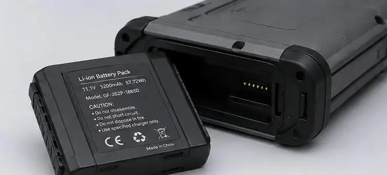
This User-Replaceable Battery Pack Design Guide covers the decisions affecting runtime, safety and maintenance. The battery should be developed together with the enclosure, connector, charger, power path and control software.
Where User-Replaceable Battery Packs Add Value
A replaceable battery architecture is useful when equipment remains in service longer than one battery life cycle, charging cannot interrupt operation or field replacement is more practical than returning the device.
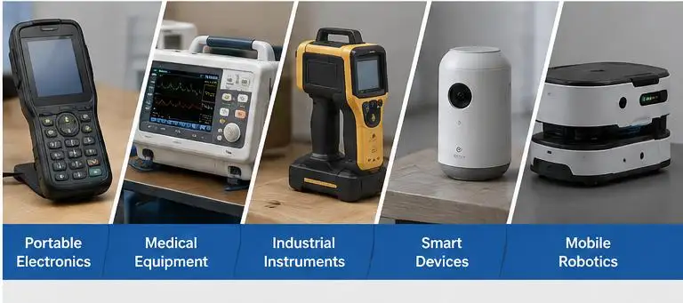
Typical applications include portable medical instruments, industrial scanners, smart devices, communication equipment and mobile robots.
A permanently installed pack may suit ultra-thin or sealed products. A hot-swappable pack permits replacement without shutdown and normally requires dual power paths or backup power.
| Architecture | Replacement Method | Power Interruption | Complexity |
| User-replaceable | Exchanged by the user | Usually yes | Moderate |
| Service-replaceable | Replaced by a technician | Usually yes | Moderate |
| Hot-swappable | Exchanged during operation | No | High |
| Permanently installed | Product disassembly required | Yes | Low–moderate |
Define the Electrical Load First
A practical User-Replaceable Battery Pack Design Guide starts with the load profile rather than the available battery cavity.
| Parameter | Required Definition |
| Nominal voltage | Normal operating voltage |
| Voltage window | Minimum and maximum acceptable input |
| Continuous current | Normal operating current |
| Peak current | Startup, motor or radio surge |
| Energy requirement | Watt-hours per duty cycle |
| Charging method | In-device, external charger or dock |
| Communication | Temperature, ID, SMBus, I²C or CAN |
Runtime ≈ Usable Battery Energy (Wh) ÷ Average Device Power (W)
Usable energy must account for conversion losses, temperature, aging and cutoff voltage. Peak current also requires separate validation because voltage sag may occur even when capacity is sufficient.
Select Chemistry Around the Duty Cycle
Chemistry affects pack size, mass, charging control, cycle life and thermal behavior.
| Chemistry | Main Strength | Design Concern |
| Li-ion | High energy density | Precise charging and protection required |
| LiFePO4 | Long life and good thermal stability | Lower cell voltage and larger volume |
| NiMH | Robust, established technology | Higher weight and self-discharge |
| Primary lithium | Long storage life | Must not be accidentally charged |
| Alkaline | Widely available | Limited high-current capability |
Also consider temperature range, discharge rate, replacement frequency, storage, transport requirements and target-market compliance.
Design the Battery Compartment as a Controlled Interface
Prevent Reverse Insertion
The battery should fit in only one valid orientation. Use asymmetric rails, offset locating features, unequal guide widths or polarized connector geometry. Printed polarity marks should support, not replace, mechanical poka-yoke features.
Control Retention and Movement
The locking system must withstand drops, transport vibration and repeated handling. Common solutions include spring latches, slide locks, push-to-release mechanisms and secondary locks.
Excess clearance can cause contact bounce, fretting wear and momentary power loss. Compartment tolerances should therefore be evaluated with connector travel and spring force.
Balance Access, Sealing and Heat
Recessed terminals reduce contact with fingers, tools and foreign metal objects. For higher IP targets, gasket compression must remain stable after repeated opening cycles. Sealing also requires thermal review because heat may accumulate during charging or high-current discharge.
Choose the Connector by Current and Insertion Life
Connector selection should reflect the actual current path, environment and replacement frequency.
| Connector Type | Suitable Use | Main Limitation |
| Spring contacts | Slide-in handheld modules | Wear and contamination |
| Blade contacts | Higher-current packs | Alignment and exposed metal |
| Plug connector | Low-cost serviceable devices | Cable pulling and misuse |
| Docking contact | Modular instruments | Tight tolerance requirements |
| Magnetic connector | Low-force user access | Retention and current limits |
Verify:
•Current carried by each contact
•Contact resistance before and after cycle testing
•Temperature rise at continuous and peak load
•Plating wear and corrosion under vibration
•Power and signal contact sequencing
•Creepage, clearance and short-circuit exposure
Coordinate BMS and Device-Side Protection
A removable lithium battery pack may require overcharge, overdischarge, overcurrent, short-circuit and temperature protection, plus cell balancing and state monitoring. A BMS does not replace system-level safety.
The device should also manage:
•Reverse polarity and incompatible-pack detection
•Inrush current during insertion
•Low-voltage warnings and controlled shutdown
•Data retention during unexpected removal
•Charger-to-pack communication
•Power-path transitions
Battery identification may use a resistor ID, EEPROM, SMBus, I²C or CAN to communicate pack model, capacity, temperature, cycle count and faults.
Replaceable vs. Hot-Swappable Design
A standard user-replaceable pack normally requires shutdown. A hot-swappable system must maintain the power rail while one pack is disconnected. This may require power OR-ing, ideal-diode controllers, dual battery bays, a supercapacitor or backup cell. Firmware must detect removal and protect stored data.
Validate Under Real Operating Conditions
A professional User-Replaceable Battery Pack Design Guide should define verification before tooling is frozen.
Key tests include:
•Correct and incorrect insertion
•Removal force and latch-cycle life
•Drop, shock and vibration retention
•Contact resistance across the insertion life
•Maximum-load and charging temperature rise
•High- and low-temperature operation
•Humidity, dust and foreign-object exposure
•Software response to sudden battery removal
Testing should use production-intent plating, springs, gaskets, plastics and enclosure tolerances. Ideal laboratory fixtures may not represent field performance.
OEM and ODM Design Checklist
Provide the battery manufacturer with:
•Nominal voltage, voltage limits and runtime target
•Continuous, peak and charging current
•Maximum dimensions, weight and connector position
•Installation direction, locking method and removal force
•Operating temperature, storage temperature and IP target
•Drop, vibration and communication requirements
•Destination market and expected annual volume
Build the Battery Around the Device Lifecycle
A successful user-replaceable design extends equipment life, reduces downtime and simplifies maintenance without weakening safety. The cells, BMS, enclosure, connector, locking system, charger and firmware should be treated as one integrated power architecture.
Develop a Replaceable Battery Pack with Gloflux
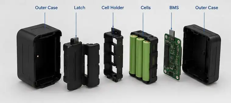
Gloflux supplies multiple options for replaceable batteries of different sizes, capacities and chemistries used in portable electronics, smart devices, medical apparatuses and various types of equipment used in industry. Each design can be optimized for the type of voltage, enclosure, connectors, communication and protection, getting a battery pack with a built-in solution for convenient replacement and stable operation of the device during extended service life. Gloflux can examine your load profile and runtime to determine the best solution for your installation constraints and operating environment, whether it be an OEM or an ODM battery pack design.
FAQs
Q1. What solutions does Gloflux offer for user-replaceable batteries?
Gloflux makes replaceable battery packs for equipment that needs convenient battery replacement and steady power output over long service periods. These battery packs come in different sizes, capacities, voltages, and battery chemistries. Custom solutions can be created for each case.
Q2. In what products can Gloflux replaceable battery packs be found?
Gloflux’s replaceable battery solutions are found in portable electronics, smart devices, medical equipment, industrial and measuring equipment and systems, and monitoring systems. Gloflux’s replaceable battery solutions decrease maintenance times by reducing the need for battery replacement.
Q3. Does Gloflux build battery packs of specific voltages and capacities?
Yes. Gloflux’s battery packs can be built to the operating voltage of the device, the continuous and peak currents, the runtime, and the available space for installation.
Q4. What battery chemistries does Gloflux provide?
Depending on the application, Gloflux will assess battery chemistries for energy density, cycle life, safe operation, discharge rate, and other physical dimensions and temperature considerations, and select which chemistry would be best. This selection is based on the complete cycle of the device.
Q5. Does Gloflux develop battery packs with custom keyboard locking systems?
Yes. Gloflux creates custom battery packs with battery enclosures, direction of battery insertion, location mechanisms, and removal and locking systems to prevent reversal of the battery pack, release of the battery pack, and to maintain electrical contact.
Talk to the Manufacturer
Resources & Insights

High Capacity Lithium Battery for Wearables: High-Voltage LiPo Cell Design
2026-10-19

Cylindrical Battery Packs for Laptops: 2S vs 3S vs 4S Battery Design
2026-10-19

Stage Lighting Battery Pack: Prevent Voltage Drop & LED Flicker
2026-10-19

Best Rechargeable Batteries for Smart Devices: Performance, Safety, and Selection Guide
2026-10-19


