


 Home /
 User-Replaceable Battery for Medical Devices: Hot-Swap and Backup Power Design


Table of Contents
A User-Replaceable Battery for Medical Devices enables trained users to replace a depleted battery without opening the main equipment enclosure. However, removability alone does not provide uninterrupted operation. A functional hot-swap system also requires a temporary energy source, controlled power-path switching, reliable battery detection, suitable connectors, and coordinated firmware.
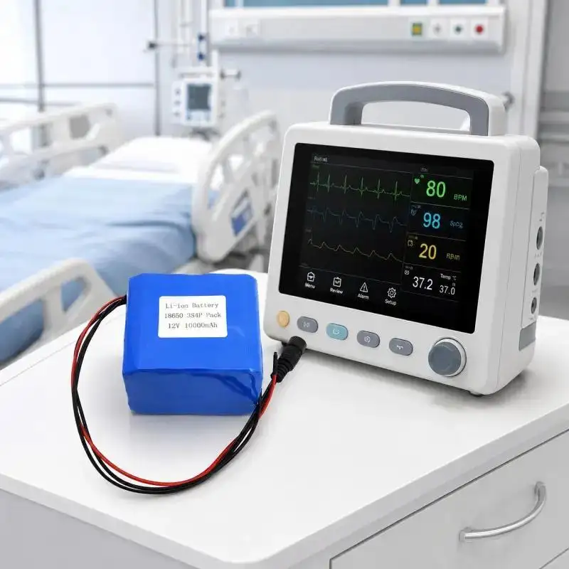
This distinction is critical for infusion pumps, patient monitors, diagnostic instruments, portable respiratory equipment, and home healthcare devices. An uncontrolled power interruption may stop therapy, reset alarms, interrupt monitoring, or erase unsaved operating data. Battery selection must therefore be integrated with the complete medical device power architecture.
What Is a User-Replaceable Battery for Medical Devices?
A User-Replaceable Battery for Medical Devices is installed in an accessible compartment and can be removed without disassembling safety-critical parts of the equipment. A practical design normally includes:
•A secure battery compartment and locking mechanism
•Polarized or keyed connectors
•Protection against accidental release
•Battery presence and voltage detection
•Clear insertion and removal guidance
•Electrical contacts rated for repeated replacement
•A battery management or protection circuit
The design improves serviceability and allows runtime to be restored quickly. It does not necessarily allow the device to continue operating while the battery is absent.
User-Replaceable, Hot-Swap and Backup Batteries
These terms describe different system functions.
| Power Design | Main Function | Operation During Replacement | Essential Components |
| User-replaceable battery | Simplifies battery replacement | Not guaranteed | Removable pack, latch and connector |
| Hot-swap battery system | Maintains power during replacement | Yes | Main battery, hold-up source and power-path controller |
| Backup battery system | Supplies power after primary-source failure | Depends on architecture | Backup pack, charger and switching circuit |
| Dual-battery system | Extends runtime and supports sequential replacement | Usually | Two monitored battery channels and controlled power sharing |
A User-Replaceable Battery for Medical Devices can form part of any of these architectures, but the device-level electronics determine whether uninterrupted switching is possible.
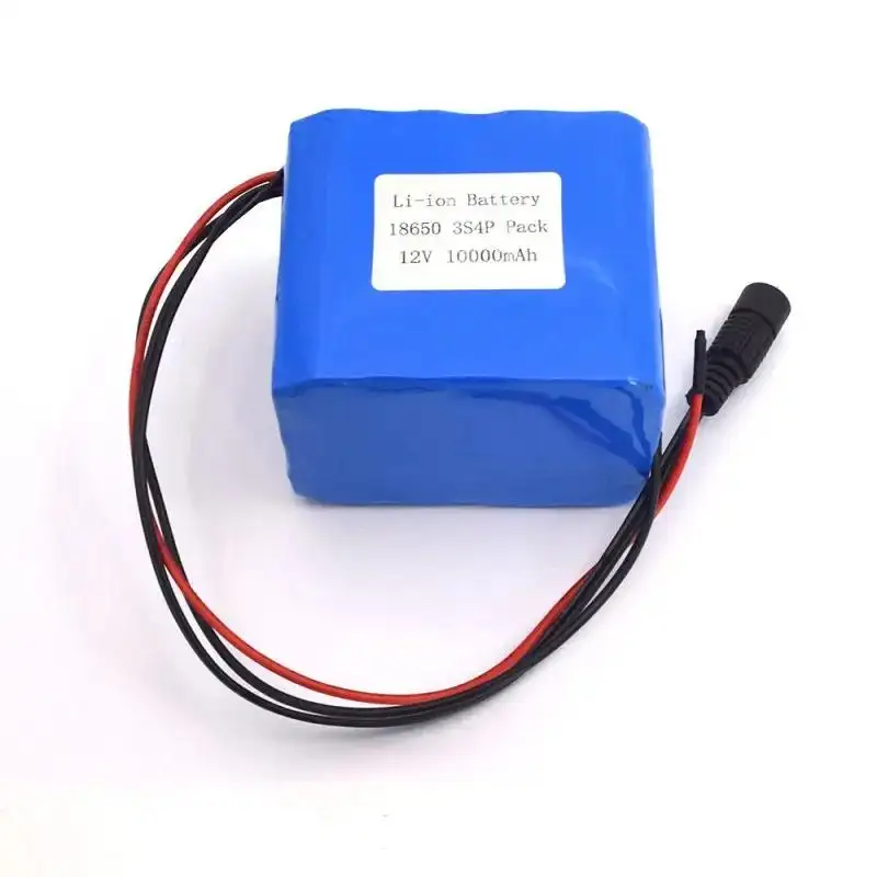
How Medical Hot-Swap Power Transfer Works
In general, almost any circumstance can utilize these five steps for battery replacement.
- Removal Detection: When battery removal is detected, like a switch or voltage change, the system is prepared for further action.
- Substitute Battery Operation: The system continues to operate with a substitute battery or reserve cell.
- Critical-Load Retention: The system allows continuous operation of the processing, alarm, memory, display, and sensing circuits with zero battery voltage.
- New-Battery Identification: The system performs type-specific tests on batteries for open circuit, fault, short circuit, temperature, etc.
- Controlled Reconnection: The path allows for battery connection with a controlled path so inrush currents and reverse currents are not allowed.
The main goal is to allow the process to continue operating until the system rail goes into undervoltage lockout or resets the processor. As determined by the system requirements, the designers will set the required hold-up time according to the load current, converter-efficiency loss, the minimum operational voltage, and the estimated time to replace the battery.
Selecting the Right Backup Architecture
| Architecture | Technical Advantage | Main Limitation | Typical Use |
| Main battery plus capacitor | Compact and fast switching | Usually supports only a short hold-up period | Low-power electronics |
| Main battery plus reserve battery | Longer replacement window | Additional charging and aging management | Infusion pumps and monitors |
| Two removable batteries | One pack can be replaced while the other powers the load | Greater size and control complexity | Continuous-duty equipment |
| AC adapter plus internal battery | Automatic transfer during mains failure | Depends on external power availability | Bedside medical devices |
| Single removable battery | Simple mechanical and electrical design | Requires shutdown for replacement | Non-critical portable equipment |
The architecture should be selected from the required backup duration rather than from battery capacity alone.
Critical Engineering Challenges
Power-Rail Stability
The backup source must maintain adequate voltage during switching. Verification should include:
•Normal, startup, and peak load currents
•DC-DC converter input range
•Processor and alarm reset thresholds
•Display and communication power requirements
•Data-retention time
•Worst-case battery and temperature conditions
Transient testing is necessary because average current measurements may not reveal brief pump-motor, wireless-transmission, alarm, or display-current peaks.
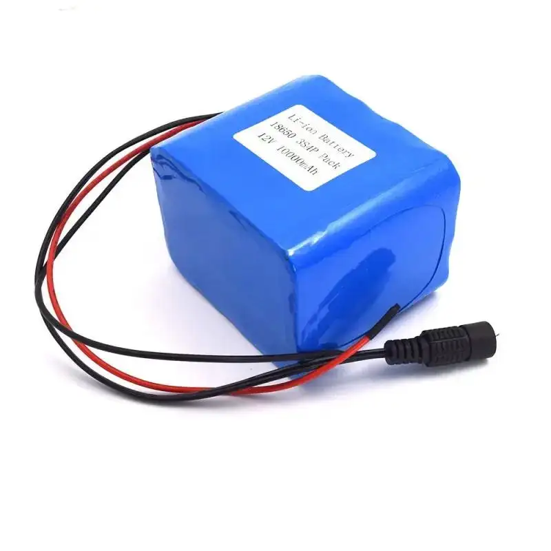
Connector Resistance and Contact Bounce
A detachable interface introduces additional resistance. Contact wear, contamination, oxidation, insufficient spring force, or repeated insertion can cause:
•Momentary voltage collapse
•Localized heating
•Incorrect low-battery warnings
•Charging losses
•Intermittent device resets
Connector ratings should cover peak current, insertion life, contact temperature rise, and the cleaning environment. Staged contacts may also be used so that ground, communication, and power lines connect in a controlled sequence.
Battery Mismatch and Reverse Current
In a dual-battery system, packs with different state of charge, terminal voltage, or internal resistance should not be directly paralleled. Otherwise, a high equalization current may flow between packs.
MOSFET-based ideal-diode circuits or dedicated power-path controllers can isolate the batteries, prioritize the preferred source, and block reverse current. Firmware should also reject a battery whose voltage or temperature is outside the permitted range.
Inrush Current
When a new battery is inserted, device input capacitors may initially appear as a low-impedance load. The resulting inrush current can produce connector arcing, contact erosion, voltage disturbance, or unintended protection-circuit activation.
Common control methods include:
•Pre-charge resistors
•Soft-start circuits
•Current-limited switches
•Controlled MOSFET turn-on
•Staged power contacts
Battery Monitoring
A smart User-Replaceable Battery for Medical Devices may report:
•State of charge
•State of health
•Pack temperature
•Cycle count
•Remaining runtime
•Battery identity
•Protection and fault status
Remaining-runtime estimates should be based on actual equipment load rather than capacity percentage alone. Pump activity, display brightness, wireless communication, battery aging, and ambient temperature can all change usable runtime.
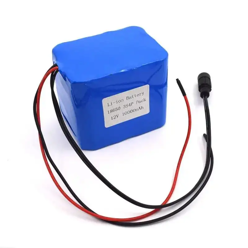
How Gloflux Supports Medical Battery Integration
Gloflux offers design services for User-Replaceable Battery for Medical Devices projects. For portable and backup-powered medical equipment, its 11.1V 10000mAh 3S4P battery provides a high capacity in a compact and rechargeable form factor.
Customization options include, but are not limited to:
•Different connector types and lengths
•Setting the protection circuit parameters
•Rigid versus wrapped configuration
•Integration of mounting and battery compartment interfaces
•Communication and monitoring functions
•Design variations for capacity and voltage
The integrated protection circuit provides some level of assurance against overcharge, over-discharge, overcurrent, and short-circuits. Hot-swap, however, relies on the design and integration of the medical device's backup source, its power-path circuit, connectors, control software, and system validation.
Building a Reliable Medical Battery System
A dependable User-Replaceable Battery for Medical Devices is not defined by capacity alone. Reliable operation requires coordinated battery protection, voltage management, controlled source switching, durable mechanical interfaces, accurate monitoring, and clear replacement procedures.
Gloflux manufactures fully configurable lithium-ion batteries for the medical technology industry. Whether you need batteries for patient monitors, infusion pumps, or other medical devices, call us to discuss your packaging needs for voltage, capacity, protection, connectors, casing, communication, and integration.
FAQs
Q1. What are some solutions to User-Replaceable Battery for Medical Devices from Gloflux?
Gloflux designs battery packs for infusion pumps, patient monitors, diagnostic tools, and respiratory equipment, as well as other medical devices. The packs can be made with the features and voltages you require. Everything from the wires, protective covers, and case adding or removing communication features can be customized.
Q2. Can Gloflux construct a battery pack to a specific medical device?
Yes, at Gloflux we can alter battery pack configurations based on voltage range, load profile, desired runtime, available space for installation, and charging and/or electrical connectivity. Customization may include protection circuitry, casing and outer shields, and the communication features of the pack.
Q3. Does a Gloflux user-replaceable battery support hot-swap operation?
No, while Gloflux batteries are designed to be easily removed and replaced, other hardware and software must be designed for hot-swap operation as well. This includes device level back-up power, a control circuit to manage the power path, battery detection circuitry, and an aligned software package.
Q4. For what medical devices would a 11.1V Gloflux battery be appropriate?
The 11.1V battery configuration can be utilized in infusion pumps, syringe pumps, portable patient monitors, diagnostic equipment, emergency medical devices, respiratory devices, mobile clinical systems, and healthcare backup power modules, after electrical validation has been done at the device level.
Q5. What other protection features can Gloflux include in a medical battery pack?
Protection circuit features can be designed for overcharge, over-discharge, and overcurrent. Short circuit protection features can also be included. The choice of protection features should be based upon the load and charging profile, wiring, connectors, and the expected or anticipated use environment.
Talk to the Manufacturer
Resources & Insights

High Capacity Lithium Battery for Wearables: High-Voltage LiPo Cell Design
2026-10-19

Cylindrical Battery Packs for Laptops: 2S vs 3S vs 4S Battery Design
2026-10-19

Stage Lighting Battery Pack: Prevent Voltage Drop & LED Flicker
2026-10-19

Best Rechargeable Batteries for Smart Devices: Performance, Safety, and Selection Guide
2026-10-19


