


 Home /
Rechargeable Battery for Smart Lock: How BLE and Wi-Fi Affect Battery Runtime


Table of Contents
- Why Real Smart Lock Runtime Can Be Much Shorter Than the Lab Estimate
- BLE Is Low Power Only When Advertising Is Properly Controlled
- Wi-Fi Runtime Depends on Sleep and Reconnection Strategy
- BLE-Only, BLE Gateway or Direct Wi-Fi
- Convert Wireless Activity Into Battery Capacity
- Reliable Unlocking at Low SOC Is a Pulse-Power Problem
- Match BMS Protection to the Lock, Not Just the Cell
- RF Placement and Battery Installation Affect the Same System
- Validate Safety and Runtime Before Production
A Rechargeable Battery for Smart Lock should never be selected from mAh alone. In a connected lock, BLE advertising, Wi-Fi beacon listening, cloud heartbeats, motor startup, biometric sensors, BMS standby current, and poor RF conditions all contribute to the real energy budget.
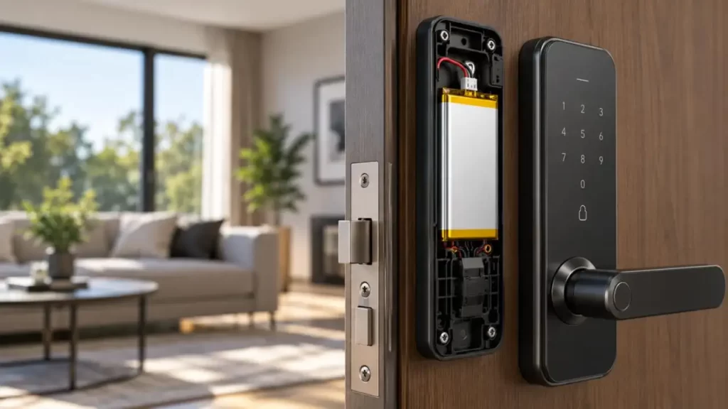
This explains why two locks using batteries with similar rated capacity can deliver very different runtime. For smart-lock OEMs, the engineering task is to match the battery to the communication architecture and actual load profile, not simply install a larger pack.
Why Real Smart Lock Runtime Can Be Much Shorter Than the Lab Estimate
Smart locks spend long periods in standby, but energy consumption is highly dynamic.
A realistic load profile includes:
• MCU and sensor sleep current
• BLE advertising and connection events
• Wi-Fi beacon/DTIM listening
• Wi-Fi association and reconnection
• Fingerprint, keypad or NFC activation
• Lock motor startup and movement
• LEDs and buzzers
• BMS quiescent current
Poor Wi-Fi coverage can make the situation worse. Weak RSSI may increase retransmissions, reconnection attempts and radio-active time.
For this reason, the runtime of a Rechargeable Battery for Smart Lock should be calculated as a system energy budget:
Daily energy ≈ Σ (Voltage × Current × Active Time)
The battery must then provide sufficient usable energy after considering temperature, aging, conversion losses and low-SOC operating limits.
BLE Is Low Power Only When Advertising Is Properly Controlled
BLE can support very low average current, but advertising configuration matters.
A shorter advertising interval:
• Improves phone discovery speed;
• Increases RF wake-up frequency;
• Increases average energy consumption.
A longer interval lowers radio duty cycle but may make the lock feel less responsive.
A more efficient smart-lock strategy is often adaptive advertising:
Long standby interval → Keypad/touch event → Fast advertising → Connection → Return to slow advertising
Connection interval and TX power also need optimization. Maximum RF output should not automatically be used when the antenna and enclosure already provide sufficient link margin.
Wi-Fi Runtime Depends on Sleep and Reconnection Strategy
Direct Wi-Fi enables cloud connectivity without an external gateway, but its battery impact depends heavily on firmware design.
Important parameters include:
• Beacon interval;
• DTIM period;
• Listen interval;
• Modem/light/deep sleep mode;
• Cloud heartbeat frequency;
• Reconnection frequency;
• RSSI and packet retry rate.
Keeping Wi-Fi connected can reduce remote-command latency, while less frequent network listening can reduce average consumption.
However, completely disconnecting Wi-Fi after every event is not always more efficient. Re-association, IP setup, security negotiation and cloud reconnection also consume energy.
The correct engineering metric is therefore:
energy per completed communication event, not simply Wi-Fi peak current.
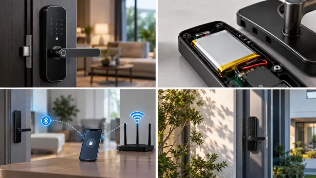
BLE-Only, BLE Gateway or Direct Wi-Fi
Communication architecture should be selected before finalizing the Rechargeable Battery for Smart Lock.
| Architecture | Battery Impact | Remote Access | Main Engineering Trade-Off |
| BLE-only | Low RF duty cycle | Nearby phone | Limited direct cloud access |
| BLE + Gateway | Low lock-side RF load | Gateway provides Internet | Additional hub required |
| Direct Wi-Fi | Higher optimization requirement | Direct cloud access | Runtime vs response latency |
| BLE + Event Wi-Fi | Wi-Fi active when required | Flexible | More firmware complexity |
A BLE gateway moves continuous Internet connectivity away from the door lock. Direct Wi-Fi simplifies system topology but places greater demands on power-management firmware and battery sizing.
Neither architecture is universally better.
Convert Wireless Activity Into Battery Capacity
Before specifying 2000 mAh, 3000 mAh or another capacity, engineers should build a measured daily duty cycle.
| Load | Required Measurement |
| System standby | Average sleep current |
| BLE | Events/day and radio-active time |
| Wi-Fi | Listening, uploads and reconnects |
| Fingerprint/keypad | Activations per day |
| Motor | Peak current and run time |
| BMS | Quiescent current |
Capacity should preferably be evaluated in Wh as well as mAh, especially when comparing different voltage platforms.
A Rechargeable Battery for Smart Lock must also retain margin for:
• Low temperature;
• Cell aging;
• Conversion losses;
• Low-SOC operation;
• Manufacturing variation.
Reliable Unlocking at Low SOC Is a Pulse-Power Problem
Smart locks differ from many low-power IoT devices because the motor creates a short but relatively high load.
During startup:
Voltage sag ≈ Peak Current × Battery Internal Resistance
As SOC decreases—or when temperature falls and cells age—internal resistance can rise. The battery may therefore have remaining capacity but still drop below the system's undervoltage threshold when the motor starts.
This is why smart-lock battery engineering must consider:
• Peak discharge current;
• Cell internal resistance;
• Minimum operating voltage;
• Motor stall current;
• Cable and connector resistance;
• BMS overcurrent threshold.
If the BMS threshold is too close to normal motor inrush current, a valid unlock command may trigger protection.
Match BMS Protection to the Lock, Not Just the Cell
A properly engineered Rechargeable Battery for Smart Lock requires coordinated electrical protection.
Typical specifications include:
• Overcharge protection;
• Over-discharge protection;
• Short-circuit protection;
• Overcurrent protection;
• NTC temperature monitoring;
• Charge-current limit;
• Cutoff voltage;
• Connector and wiring specification.
From Gloflux's engineering perspective, these requirements should be defined during battery-pack development rather than added after mechanical design is frozen.
Gloflux supports custom BMS protection, wiring, connectors, charging interfaces, enclosures and optional SMBus, I²C and CAN communication. Custom LiPo dimensions are also available, with listed minimum thickness options down to 3 mm for space-constrained designs.
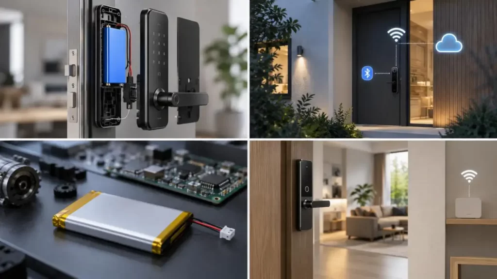
RF Placement and Battery Installation Affect the Same System
Battery and antenna design should not be reviewed independently.
Metal doors, internal brackets and battery placement may influence antenna performance. A poorly positioned antenna can lead to more retries and longer radio-on time, indirectly reducing battery runtime.
Mechanical validation should therefore cover:
• Antenna-to-battery spacing;
• Metal enclosure shielding;
• Battery L × W × H;
• Cable voltage drop;
• Connector contact resistance;
• Charging-port accessibility;
• Removable-pack serviceability;
• Thermal and moisture exposure.
A larger battery that compromises antenna placement may not deliver the expected system-level improvement.
Validate Safety and Runtime Before Production
Battery qualification and wireless-device compliance are separate tasks. Depending on configuration and destination market, projects may need requirements related to IEC 62133-2, UN 38.3, UL, CE or other applicable standards.
Runtime validation should also include:
• High/low SOC motor-start testing;
• Weak-RSSI Wi-Fi operation;
• Repeated reconnection testing;
• Low-temperature discharge;
• Charge/discharge cycling;
• Abnormal motor-stall conditions.
Gloflux states that its customization workflow covers cell sourcing, engineering design, prototype testing and mass production, supported by 60+ quality inspection procedures. Its manufacturing base is listed at 30,000 m², with daily production capacity above 350,000 units.
Final Words
The correct development sequence is:
Wireless architecture → Duty-cycle measurement → Energy budget → Peak-load analysis → Voltage/capacity selection → BMS matching → Mechanical integration → Validation → Mass production.
For smart-lock developers, this system-level approach is more reliable than simply increasing battery capacity. Gloflux provides custom Li-ion, LiPo and complete battery-pack development covering cell selection, BMS design, mechanical integration, prototyping, certification support and volume production. For a new Rechargeable Battery for Smart Lock project, the best starting point is a measured device power profile and clearly defined mechanical envelope.
FAQs
Q1. Can Gloflux customize a Rechargeable Battery for Smart Lock?
Yes. Gloflux supports custom rechargeable battery development based on voltage, capacity, battery dimensions, discharge requirements, connector type, charging interface, enclosure, and BMS functions.
Q2. Can Gloflux design a battery for BLE and Wi-Fi smart locks?
Yes. Battery specifications can be matched to the smart lock's actual operating profile, including BLE advertising, Wi-Fi communication, standby current, motor operation, and required runtime.
Q3. What information should I provide Gloflux for a smart lock battery project?
Useful information includes nominal voltage, target capacity, motor peak current, standby current, BLE/Wi-Fi architecture, battery dimensions, charging method, operating temperature, connector requirements, and target market.
Q4. Can Gloflux customize the BMS for a Rechargeable Battery for Smart Lock?
Yes. Gloflux can integrate protection functions such as overcharge, over-discharge, overcurrent, and short-circuit protection. Temperature monitoring and communication functions can also be considered according to project requirements.
Q5. Can Gloflux provide thin LiPo batteries for compact smart lock designs?
Yes. Gloflux supports custom LiPo battery dimensions for space-constrained applications, making them suitable for compact smart lock housings and narrow battery compartments.
Talk to the Manufacturer
Resources & Insights
High Capacity Lithium Battery for Wearables: High-Voltage LiPo Cell Design
2026-10-19
Cylindrical Battery Packs for Laptops: 2S vs 3S vs 4S Battery Design
2026-10-19
Stage Lighting Battery Pack: Prevent Voltage Drop & LED Flicker
2026-10-19
Best Rechargeable Batteries for Smart Devices: Performance, Safety, and Selection Guide
2026-10-19


