


 Home /
 Common Coating Defects: Causes, Troubleshooting Methods, and Practical Solutions


Table of Contents
- 1. Transverse Stripes
- 2. Longitudinal Streaks
- 3. Orange-Peel Surface
- 4. Bubbles
- 5. Craters
- 6. Point-Shaped Missing Coating
- 7. Thick Coating Edges
- 8. Hard Particles or Crystal Points
- 9. Periodic Transverse Thick and Thin Bands
- 10. Rainbow Patterns
- 11. Pinholes Arranged in a Chain
- 12. Raised Volcano-Shaped Defects
- 13. Drying Cracks
- 14. Electrostatic Pitting
- 15. Swelling Marks
- Building a Systematic Troubleshooting Process
Coating quality directly affects the performance, appearance, and production yield of lithium batteries, optical films, protective films, medical tapes, separators, and other functional materials. Even a small coating defect can cause poor adhesion, uneven thickness, reduced electrical performance, visible appearance problems, or complete product rejection.
Effective troubleshooting requires more than simply adjusting machine parameters. Engineers must observe the defect shape, measure its spacing, compare it with the coating speed, inspect the slurry and substrate, and determine whether the source comes from mechanical vibration, contamination, drying, static electricity, or material compatibility.
Below are 15 common coating defects, together with their typical causes and practical corrective actions.
1. Transverse Stripes
Transverse stripes appear as alternating light and dark bands across the width of the web. The spacing is normally uniform, creating a zebra-like pattern. This defect indicates periodic coating-thickness variation and is especially common in comma-blade coating.
Rotating components are often suspected first. However, engineers should not replace parts without verifying the relationship between stripe spacing and web speed. Reducing the coating speed can help identify whether the defect comes from a fixed-speed rotating component or a web-synchronized roller.
In one case, the stripe spacing became smaller after the coating speed was reduced. Inspection with a strong flashlight eventually revealed slight vibration in the backing-roll bearing housing.
The solution was to replace the bearing and recalibrate roll runout. A good preventive measure is to check backing-roll runout monthly with a dial indicator and stop the machine immediately when the measured value exceeds the permitted tolerance.
2. Longitudinal Streaks
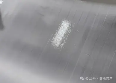
Longitudinal streaks are continuous or intermittent lines that run in the machine direction. They usually occur when a specific area of the coating head or blade delivers an abnormal amount of slurry.
Common causes include blade damage, local blade wear, dried slurry, or large foreign particles trapped at the coating gap. In one optical-film application, a hairline streak appeared near the center of the web. Inspection under magnification showed a 0.1 mm chip on the comma blade.
Further investigation found that the operator had replaced a 50-micron filter with a 150-micron filter to increase flow speed. Large particles passed through the system and damaged the blade.
The blade was replaced, the original filter was restored, and a magnetic filter was added to the supply line. Filter specifications should never be changed without formal engineering approval.
3. Orange-Peel Surface
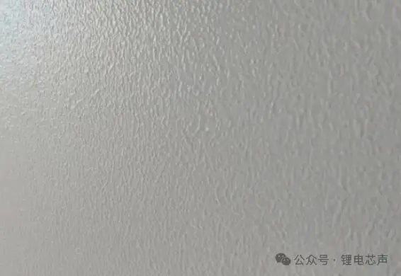
An orange-peel defect creates a rough surface covered with small peaks and depressions. It often results from poor leveling or excessively rapid solvent evaporation.
This problem can occur in micro-gravure, comma-blade, and slot-die coating. In a water-based coating process, the defect appeared mainly on sunny days. Surface-temperature measurements showed that the coating entered the oven approximately 5°C hotter than expected because sunlight and ventilation changed the local oven heat load.
The surface dried too quickly and formed a skin, while solvent remained trapped inside the coating.
The production line added a water-cooled roller before the oven, reduced the temperature of the first drying zone, and extended the low-temperature drying stage. Solvent needs sufficient time to escape. Aggressive initial heating often damages leveling rather than improving productivity.
4. Bubbles
Bubbles appear as round cavities on or inside the coating. Larger bubbles are visible to the naked eye, while smaller ones may require magnification.
Incomplete slurry degassing is a common cause, but air can also enter through pumps, seals, fittings, or negative-pressure sections of the supply system. In one medical-tape line, the vacuum degassing parameters were correct, yet the bubble rate increased sharply.
A damaged pump seal was drawing air into the slurry. Because the pump was installed below floor level, the long suction section created strong negative pressure.
The seal was replaced, the pump position was raised, and the negative-pressure pipe length was reduced. Operators should inspect transparent supply pipes and check for visible bubbles during every shift.
5. Craters
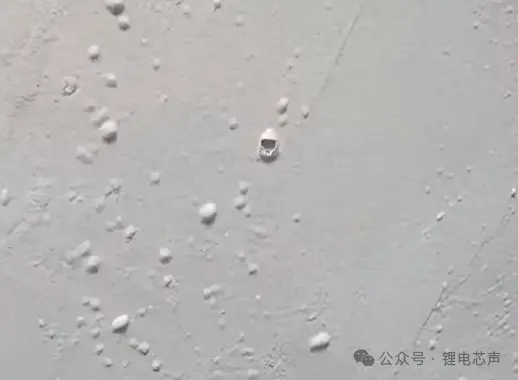
A crater is a circular depression with a low center and raised edge. It forms when a low-surface-tension contaminant pushes the surrounding coating away.
Typical contaminants include silicone oil, grease, release agents, fingerprints, and volatile chemicals. In one optical-film factory, craters appeared after switching to a new batch of PET substrate. The supplier’s report showed acceptable surface tension, but contact-angle testing found abnormal values.
The film had been stored near lubricant containers, allowing volatile silicone compounds to adsorb onto the surface.
The contaminated material was rejected, and the supplier was required to separate chemicals from substrate storage. Incoming inspection should include surface-energy or contact-angle testing at several points on every roll.
6. Point-Shaped Missing Coating
This defect appears as randomly distributed white or transparent dots, similar to needle marks. Dust, fibers, or particles on the substrate prevent the coating liquid from spreading evenly.
In a polarizer coating line, the white-dot rate suddenly increased from 0.1% to 2%. Microscopic inspection found a blue fiber at the center of each defect. Only personnel outside the cleanroom wore blue clothing, indicating a gowning-control problem.
The factory strengthened entry procedures, added tacky mats in the buffer area, and installed ionizing air bars and adhesive cleaning rollers before coating.
Particle analysis is essential because the shape and color of the contaminant can often reveal its source.
7. Thick Coating Edges
Thick edges appear when the left and right sides of the coating become thicker than the center. The raised edges can cause wrinkles, telescoping, and uneven pressure during winding.
Surface tension causes liquid to migrate and accumulate near the coating boundary. Tight side dams can also create turbulence and increase edge buildup.
One effective solution is to maintain a small gap, such as 0.3 mm, between the side dam and blade end. The blade ends can also be ground with a narrow chamfer to reduce edge thickness.
Another common practice is to coat several millimeters wider than the finished product and trim the thick edge before final winding. This creates some material waste but greatly improves winding stability.
8. Hard Particles or Crystal Points
Crystal points are small, hard projections on the coating surface. They may cast shadows under strong light and can damage downstream cutting or laminating tools.
They usually come from gel particles, undissolved resin, crystallized additives, or poorly dispersed solids. In a high-viscosity pressure-sensitive adhesive process, standard filtration and dispersion checks showed no problem. After the slurry remained still for 24 hours, however, crystals appeared at the bottom of the tank.
Low temperature had caused part of the resin to precipitate.
The tank was equipped with a temperature-controlled jacket and maintained at 25 ± 2°C. Continuous circulation was added to prevent dead zones. Temperature control is as important as filtration in systems that contain temperature-sensitive resins.
9. Periodic Transverse Thick and Thin Bands
This defect appears as separate thick or thin bands at fixed intervals along the web. Unlike continuous transverse stripes, these bands look like repeated wheel marks.
The most common causes are backing-roll eccentricity, roller deformation, imbalance, or bearing damage. A feeler gauge or dial indicator can help detect variation as the roll rotates.
In one case, the backing roll had approximately 0.1 mm eccentricity and a 15 g dynamic imbalance. The roll was reground and dynamically balanced.
Backing rolls should receive scheduled maintenance, and their runout should be checked before changing to a high-precision product.
10. Rainbow Patterns
Rainbow patterns resemble the colors seen on an oil film. Their appearance changes with the viewing angle.
This defect is common in optical coatings, anti-reflection layers, and fingerprint-resistant coatings. It results from thin-film interference caused by very small thickness differences.
In one case, the measured thickness variation was only a few nanometers, yet the customer could clearly see color changes. The problem was not simply poor uniformity. The selected absolute coating thickness fell within a highly sensitive optical-interference range.
The solution was to adjust the target thickness away from that sensitive region. Optical coating development must consider both thickness uniformity and the relationship between thickness and visible-light wavelength.
11. Pinholes Arranged in a Chain
A pinhole chain consists of evenly spaced holes arranged in a straight line or arc. This pattern usually points to damage on a coating roller.
A dent, pit, or scratch can retain a small amount of liquid and transfer the same mark repeatedly to the web. In a battery-separator line, the arc of the pinhole pattern matched the circumference of the micro-gravure roller.
Inspection revealed a small dent caused by an operator using a metal scraper during cleaning.
The damaged roller had to be replaced. Cleaning procedures were revised to permit only nonwoven cloths, approved solvents, and plastic tools.
12. Raised Volcano-Shaped Defects
Unlike a crater, this defect has a raised center surrounded by a depressed area. It often forms when a large particle becomes trapped between the blade and the substrate.
The blade pushes the particle forward, leaving an uncoated region behind it. The slurry then flows back into the empty area and accumulates around the particle.
Corrective actions include improving filtration, reducing slurry viscosity within the permitted formulation range, and adjusting the blade angle. In one thick-coating process, filtration was upgraded from 100 mesh to 200 mesh, and the blade angle was reduced from 15 degrees to 8 degrees.
13. Drying Cracks
Drying cracks form an irregular network resembling dried mud. They occur when drying shrinkage stress exceeds the cohesive strength of the coating.
High-solid formulations, thick wet coatings, and excessive oven temperature increase the risk. Rapid airflow can also make the problem worse by drying the surface faster than the inner layer.
A ceramic coating with a 200-micron wet thickness cracked immediately after entering the oven. The successful solution used staged drying: approximately 40°C in the first zone, 60°C in the middle zone, and 80°C in the final zone.
Other options include reducing single-pass thickness, applying two thinner layers, or adding a compatible leveling agent. Once severe drying cracks form, they normally cannot be repaired.
14. Electrostatic Pitting
Electrostatic pitting appears as radial or tree-like marks that resemble electrical burns. It occurs when charge accumulates on an insulating substrate and suddenly discharges through the wet coating.
The defect becomes more common in dry weather, at high web speeds, and when coating PET or other insulating films. Static electricity is not only a quality problem but also a serious fire hazard in solvent-based processes.
Factories should install ionizing bars before and after coating, ensure reliable equipment grounding, monitor static voltage, and maintain suitable workshop humidity. Reducing winding tension and friction can also help control charge generation.
15. Swelling Marks
Swelling marks appear as smooth, raised areas that may develop immediately or after storage. They often result from plasticizer or residual-solvent migration from the substrate into the coating.
This defect is particularly difficult because the product may pass initial inspection and fail several months later. Accelerated aging at elevated temperature and humidity can reveal compatibility problems before shipment.
The most effective solution is to select a low-migration substrate and introduce heat-and-humidity aging into the qualification and outgoing inspection process.
Building a Systematic Troubleshooting Process
Coating defects rarely disappear through random parameter adjustment. A more effective method is to record the defect shape, direction, spacing, frequency, location, and response to speed changes. Engineers should then inspect the coating head, rollers, bearings, filtration system, slurry condition, substrate cleanliness, oven profile, static control, and material compatibility.
Preventive controls such as roll-runout inspection, filter management, temperature control, incoming substrate testing, cleanroom discipline, and accelerated aging can prevent many defects before production begins.
The most valuable troubleshooting principle is simple: the defect pattern contains information. When engineers connect that pattern with machine speed, roller circumference, slurry behavior, drying conditions, and contamination sources, they can identify the true cause faster and reduce unnecessary downtime, material waste, and repeated quality failures.
Talk to the Manufacturer
Resources & Insights

High Capacity Lithium Battery for Wearables: High-Voltage LiPo Cell Design
2026-10-19

Cylindrical Battery Packs for Laptops: 2S vs 3S vs 4S Battery Design
2026-10-19

Stage Lighting Battery Pack: Prevent Voltage Drop & LED Flicker
2026-10-19

Best Rechargeable Batteries for Smart Devices: Performance, Safety, and Selection Guide
2026-10-19


