


 Home /
 Lithium-Ion Battery Electrode Calendering Process: Parameter Control, Defect Analysis, and Intelligent Manufacturing Trends


Table of Contents
- What Is the Electrode Calendering Process?
- Preparations Before Electrode Calendering
- How to Determine the Roller Gap and Compression Ratio
- Standard Electrode Calendering Procedure
- Why Calendering Pressure Must Not Be Too High or Too Low
- How Roller-Gap Accuracy Affects Cell Consistency
- Common Calendering Defects and Their Solutions
- Calendering Challenges for Silicon-Carbon Anodes
- Calendering Development for Solid-State Battery Electrodes
- The Intelligent Transformation of Electrode Calendering
- Conclusion
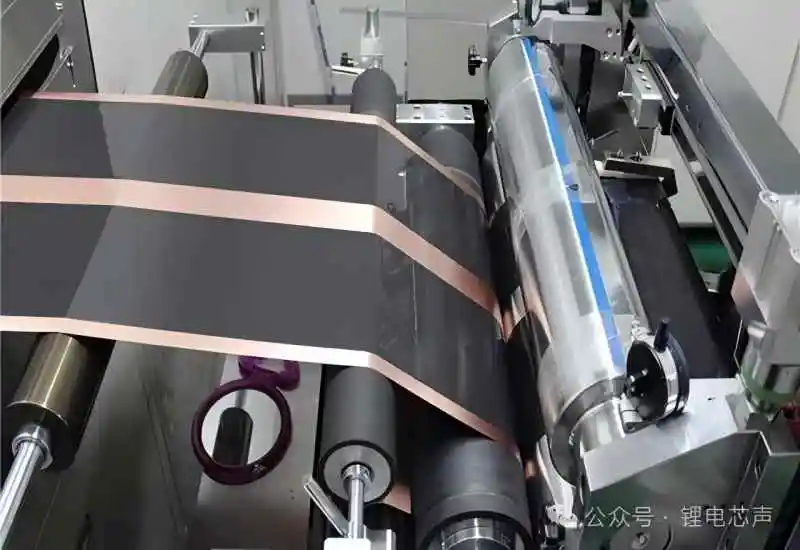
In lithium-ion battery manufacturing, electrode calendering is a critical process that connects coating and drying with slitting, winding, or stacking. The quality of calendering directly affects electrode thickness, compaction density, porosity, internal resistance, energy density, rate performance, cycle life, and cell consistency.
As power batteries, energy storage batteries, medical device batteries, and consumer electronics batteries continue to move toward higher energy density, traditional calendering methods based mainly on operator experience are no longer sufficient. Modern electrode calendering is developing toward higher precision, online inspection, automated adjustment, and closed-loop control.
What Is the Electrode Calendering Process?
Electrode calendering refers to the process of applying pressure to a coated and dried positive or negative electrode sheet through a pair of counter-rotating rollers. The pressure rearranges the active material particles and increases the density of the electrode coating.
The process has three primary objectives.
The first objective is to increase electrode compaction density. Under the same material formulation and coating thickness, a suitable increase in compaction density allows more active material to be loaded into a limited cell volume, thereby improving volumetric energy density.
For example, increasing the compaction density of a lithium iron phosphate cathode from approximately 2.2 g/cm³ to 2.4 g/cm³ can significantly increase the amount of active material within the same volume. However, the actual capacity improvement also depends on material particle size, electrode areal loading, pore structure, and electrolyte wettability.
The second objective is to improve electrical contact among particles. After appropriate calendering, the active material, conductive additive, and binder come into closer contact. This shortens electron transmission paths and helps reduce electrode contact resistance and overall cell resistance.
The third objective is to control electrode thickness. High-precision calendering equipment can maintain thickness variation at the micrometer level, providing a stable dimensional foundation for subsequent slitting, winding, and stacking processes.
Customers looking for customized lithium-ion batteries, lithium polymer batteries, or specialized battery solutions can visit the GLOFLUX official website for additional product and customization information.
Preparations Before Electrode Calendering
Stable calendering quality depends on accurate equipment calibration and careful inspection of the electrode sheet before production. The rollers, electrode condition, and process parameters should all be verified before continuous operation begins.
Roller Surface and Parallelism Inspection
Cathode sheets usually use highly polished mirror-finished rollers to reduce surface indentations and local coating defects. Anode sheets may use either mirror-finished or slightly textured rollers, depending on the material formulation, binder performance, and adhesion between the coating and copper foil.
The two ends of the rollers must remain highly parallel. If the roller gap differs from one side to the other, the electrode may develop uneven thickness, insufficient compaction, or excessive pressure along the edges.
Before production, operators can use dial indicators, thickness gauges, or standard test sheets to verify roller-gap consistency. For high-precision battery production, the difference between the two roller ends should be controlled within a micrometer-level range whenever possible.
Electrode Coating Quality Inspection
Before entering the calendering machine, the electrode surface should be checked for bubbles, exposed foil, particles, scratches, powder shedding, and abnormal coating thickness.
Calendering cannot repair serious coating defects. In many cases, high pressure enlarges existing problems. Local particles, bubbles, or exposed foil areas may cause coating cracks, electrode breakage, or even roller damage.
Abnormal sections should therefore be marked in advance and removed, isolated, or rejected according to the quality control standard.
Moisture Content and Solvent Residue
The electrode sheet must be adequately dried before calendering. Excessive residual NMP solvent in cathode coatings may cause coating slippage, roller sticking, or local deformation under pressure.
Excessive moisture may also affect electrolyte filling, formation, and long-term electrochemical stability. Manufacturers should control electrode drying conditions by using moisture analyzers, drying ovens, or online detection systems according to the material system and product requirements.
How to Determine the Roller Gap and Compression Ratio
The roller gap is one of the most important parameters in the calendering process. An initial reference value can be calculated according to the dry electrode thickness before calendering and the target compression ratio:
Roller gap reference value = dry electrode thickness before calendering × target compression ratio
The compression ratio is the ratio of the electrode thickness after calendering to the thickness before calendering. A common reference range is approximately 0.8 to 0.9, although the correct value varies significantly among different material systems.
Lithium iron phosphate, ternary cathode materials, lithium cobalt oxide, graphite, and silicon-carbon anodes all have different particle structures and compressibility. Therefore, they should not use identical pressure and roller-gap settings.
Before mass production, manufacturers should conduct small-batch trials and establish relationships among pressure, thickness, compaction density, porosity, and peel strength. These results can then be used to define a suitable process window.
Standard Electrode Calendering Procedure
Step 1: Electrode Feeding and Tension Adjustment
The electrode sheet generally travels through the unwinding unit, guide rollers, calendering rollers, tension rollers, and rewinding unit.
During feeding, the electrode should remain centered within the roller width. Lateral deviation can create uneven edge pressure and increase the risk of wrinkles and misalignment.
Tension should be adjusted according to the current collector thickness, electrode width, and material strength. Aluminum and copper foils are relatively thin, so excessive tension may stretch the current collector and change the electrode dimensions and thickness. Insufficient tension may cause vibration, offset, or uneven winding.
Step 2: Pre-Calendering Test
Before continuous production begins, waste sheets or test electrodes should be used for trial operation and pre-calendering.
Operators should start with relatively low pressure and gradually increase it while measuring thickness, compaction density, and surface condition after each adjustment.
Establishing a pressure-versus-compaction curve helps prevent excessive pressure from being applied at once. This reduces the risk of coating cracks, powder shedding, and current collector deformation.
Step 3: Continuous Calendering
After the equipment reaches a stable operating condition, continuous calendering can begin. During production, operators should continuously observe electrode alignment, tension variation, roller temperature, and rewinding quality.
The coating edge should not run too close to the roller edge, because uneven pressure can cause excessive edge compression or cracking. A suitable safety margin should be maintained, especially for thick coatings or brittle electrode materials.
Roller temperature also affects coating deformation. Temperature changes may alter binder softness and particle rearrangement behavior. For this reason, roller temperature should remain stable during production.
Room-temperature calendering is often performed at approximately 25 ± 5°C, but the actual setting should be selected according to the material system and equipment design.
Step 4: In-Process Quality Monitoring
During continuous production, the thickness of the electrode should be measured regularly at the beginning, middle, and end of the roll. Thickness consistency should also be checked across the left side, center, and right side of the electrode.
In addition to thickness, the following indicators should be monitored:
- Electrode compaction density
- Coating porosity
- Coating peel strength
- Electrode elongation
- Surface cracks and wrinkles
- Edge powder shedding
- Rewinding alignment
If thickness continuously exceeds the tolerance limit, production should be stopped. The roller gap, hydraulic or servo pressure system, roller parallelism, electrode tension, and incoming coating thickness should then be inspected.
Step 5: Rewinding and Stress Release
The rewinding tension is generally set slightly lower than the unwinding tension to reduce electrode curling and internal mechanical stress.
Freshly calendered electrodes should not always be sent immediately to precision slitting. Allowing the electrode to rest helps release internal stress within the coating and current collector.
This can reduce edge powder shedding, burr formation, and electrode warping during slitting. The required resting time depends on the material, environmental conditions, and production schedule. For some products, approximately two hours may be used as a reference.
Why Calendering Pressure Must Not Be Too High or Too Low
Calendering pressure determines the final compaction density and pore structure of the electrode. However, higher pressure does not always produce better battery performance.
Problems Caused by Insufficient Pressure
When calendering pressure is too low, the coating remains relatively loose and particle contact is insufficient. This may result in:
- Excessive electrode thickness
- Low volumetric energy density
- High particle contact resistance
- Weak coating structural stability
- Unstable particle contact during cycling
A relatively high porosity may improve electrolyte infiltration. However, if particle-to-particle contact is poor, long-term cycle stability and cell consistency may be negatively affected.
Problems Caused by Excessive Pressure
Excessive pressure may over-compress the coating and damage its original pore structure. This may cause:
- Reduced electrolyte wetting speed
- Increased lithium-ion transport resistance
- Lower fast-charging performance
- Lower high-rate discharge performance
- Coating cracks or delamination
- Current collector elongation or deformation
- Unstable electrode springback
The calendering process must therefore balance compaction density, porosity, electrical conductivity, electrolyte wettability, and mechanical strength.
How Roller-Gap Accuracy Affects Cell Consistency
Electrode thickness is a key factor affecting cell assembly dimensions and active material loading. Even a roller-gap variation of only a few micrometers may cause noticeable changes in thickness and compaction density.
For example, if the target electrode thickness is 100 μm but the actual thickness increases to 103 μm, the compaction density may decrease. This can also affect wound-cell diameter, stacked-cell height, and active material loading per unit area.
When electrode thickness varies significantly within the same production batch, the completed cells may show differences in capacity, internal resistance, and operating temperature. These differences reduce the overall consistency of the battery pack.
Modern high-precision calendering machines typically use servo motors to control the roller gap and standard test sheets for calibration. Some systems provide roller-gap adjustment resolution down to approximately 0.1 μm, supporting more consistent electrode production.
Common Calendering Defects and Their Solutions
Uneven Electrode Thickness
Possible causes include poor roller parallelism, inconsistent roller-gap settings, incoming coating thickness variation, or electrode misalignment.
The solution is to recalibrate roller parallelism, review coating thickness data, and adjust the web-guiding and tension-control systems.
Coating Cracks
Cracking is usually related to excessive pressure, excessive coating thickness, insufficient binder content, over-drying, or brittle electrode materials.
Pressure can be reduced, staged calendering can be introduced, and the slurry formulation, binder ratio, and drying conditions should be reviewed.
Powder Shedding
Powder shedding may result from uneven binder distribution, weak adhesion between the coating and current collector, abnormal roller surfaces, or unsuitable calendering pressure.
Manufacturers should inspect slurry dispersion, current collector surface treatment, coating and drying conditions, and roller cleanliness.
Electrode Wrinkles
Wrinkles are commonly caused by unstable tension, uneven pressure on the two roller sides, electrode misalignment, or excessive rewinding tension.
The unwinding and rewinding tension should be readjusted, guide roller positions should be inspected, and roller parallelism should be confirmed.
Roller Sticking
Roller sticking may occur because of excessive solvent residue, incomplete drying, high roller temperature, or contamination on the roller surface.
Possible solutions include improving drying conditions, reducing roller temperature, cleaning the roller surface, and optimizing the binder and slurry system.
Edge Powder Loss or Edge Cracking
Edge defects may be caused by uneven coating-edge thickness, pressure concentration near the roller edge, or lateral electrode offset.
A wider edge safety margin can be maintained, the coating tapering area can be optimized, and the alignment and pressure-distribution systems can be adjusted.
Electrodes with obvious cracks, exposed foil, delamination, or severe thickness deviations should not be repaired manually and reused in commercial cells.
For mass production, defective electrodes should be isolated and rejected according to the established quality standard to avoid potential performance and safety risks.
Calendering Challenges for Silicon-Carbon Anodes
Silicon-carbon anodes have a much higher theoretical capacity than conventional graphite anodes, but silicon also undergoes significant volume expansion during charging and discharging.
This places stricter requirements on electrode porosity, mechanical strength, and coating integrity.
A staged-pressure calendering method can be used for silicon-carbon anodes. A relatively low pressure is applied first to allow initial particle rearrangement. Pressure is then gradually increased until the target compaction density is reached.
This method reduces particle breakage, coating cracking, and powder shedding caused by a single high-pressure step.
Some advanced systems can also adjust pressure distribution across the electrode width. Slightly lower pressure may be applied near the edges than in the center to improve edge quality and reduce thickness differences.
Roller sticking can be reduced by optimizing roller surface coatings, electrode moisture content, binder selection, and slurry formulation.
Calendering Development for Solid-State Battery Electrodes
Solid-state batteries use solid electrolytes instead of conventional liquid electrolytes. Their electrode and electrolyte layers are often more brittle and sensitive to mechanical stress.
Excessive calendering pressure may create microcracks within the solid electrolyte layer, increase interface resistance, or cause local contact failure.
Solid-state battery electrodes therefore require gentler and more accurate pressure control. Low-pressure calendering may be combined with hot pressing, sintering, or other interface-treatment processes to improve contact between the electrode and solid electrolyte.
The correct pressure and temperature conditions depend on whether the battery uses a sulfide, oxide, or polymer solid electrolyte. Conventional liquid-electrolyte lithium-ion battery parameters should not be applied directly without validation.
The Intelligent Transformation of Electrode Calendering
Traditional calendering systems rely heavily on operators adjusting equipment according to offline measurement results. This approach may result in delayed correction and batch-to-batch variation.
New-generation intelligent calendering systems combine servo direct-drive technology, online laser thickness measurement, data acquisition, and closed-loop control.
Servo Direct-Drive Calendering Machines
Servo direct-drive systems can adjust pressure and roller gaps quickly and accurately, reducing errors caused by mechanical transmission clearance.
For silicon-carbon anodes, high-nickel cathodes, and high-loading electrodes, servo systems can also support multi-stage pressure control and gradient-pressure calendering.
This improves the consistency of electrode thickness and compaction density.
Online Laser Thickness Measurement
Online laser thickness gauges continuously measure electrode thickness at different positions and transmit the data to the control system in real time.
When the system detects a deviation from the target thickness, it can automatically adjust the roller gap, pressure, or web tension.
This creates a closed-loop system integrating measurement, analysis, and adjustment.
Compared with traditional sampling inspection, online thickness measurement identifies process drift earlier, improves product qualification rates, and reduces the risk of large-scale rejection.
Data-Driven Process Management
Intelligent calendering systems can also record material batch data, pressure curves, roller-gap changes, roller temperature, web tension, and thickness measurement results.
By analyzing these data, manufacturers can build process databases for different electrode materials and battery models.
This reduces dependence on operator experience and improves the efficiency of new product development and pilot production.
Conclusion
Electrode calendering may appear to be a simple mechanical compression process, but it involves material properties, slurry formulation, electrode drying, roller accuracy, pressure control, tension control, and online inspection.
Insufficient pressure may reduce compaction density and weaken particle contact. Excessive pressure may damage the pore structure and reduce electrolyte wettability.
Only by establishing a suitable process window according to the electrode material, areal loading, battery application, and rate-performance requirements can manufacturers achieve the proper balance among energy density, internal resistance, fast-charging capability, cycle life, and safety.
As servo control, online laser thickness measurement, and automatic closed-loop adjustment technologies continue to develop, electrode calendering will gradually transition from experience-based production to digital and intelligent manufacturing.
GLOFLUX focuses on lithium-ion batteries, lithium polymer batteries, and customized battery solutions. Battery products can be developed according to equipment space, voltage, capacity, discharge current, and operating environment.
For more information about battery products and customization services, visit https://www.gloflux.com/.
Talk to the Manufacturer
Resources & Insights

High Capacity Lithium Battery for Wearables: High-Voltage LiPo Cell Design
2026-10-19

Cylindrical Battery Packs for Laptops: 2S vs 3S vs 4S Battery Design
2026-10-19

Stage Lighting Battery Pack: Prevent Voltage Drop & LED Flicker
2026-10-19

Best Rechargeable Batteries for Smart Devices: Performance, Safety, and Selection Guide
2026-10-19


