


 Home /
Replaceable Battery for Handheld Devices: How Mechanical Tolerances Affect Battery Fit


Table of Contents
- How Tolerance Stack-Up Determines Battery Fit
- Critical Mechanical Interfaces in Replaceable Battery Design
- Manufacturing Precision: From Prototype to Production
- GLOFLUX Manufacturing and Dimensional Control
- How Mechanical Tolerances Affect Electrical Reliability
- How to Validate Battery Fit Before Mass Production
A Replaceable Battery for Handheld Devices may operate correctly in prototype testing yet develop insertion resistance, loose retention, or intermittent electrical contact during mass production. The cause is often not battery capacity or BMS performance, but accumulated dimensional variation between the battery enclosure and host device.
For handheld scanners, mobile POS terminals, and portable instruments, mechanical tolerances must control insertion clearance, connector alignment, locking engagement, and long-term interchangeability.
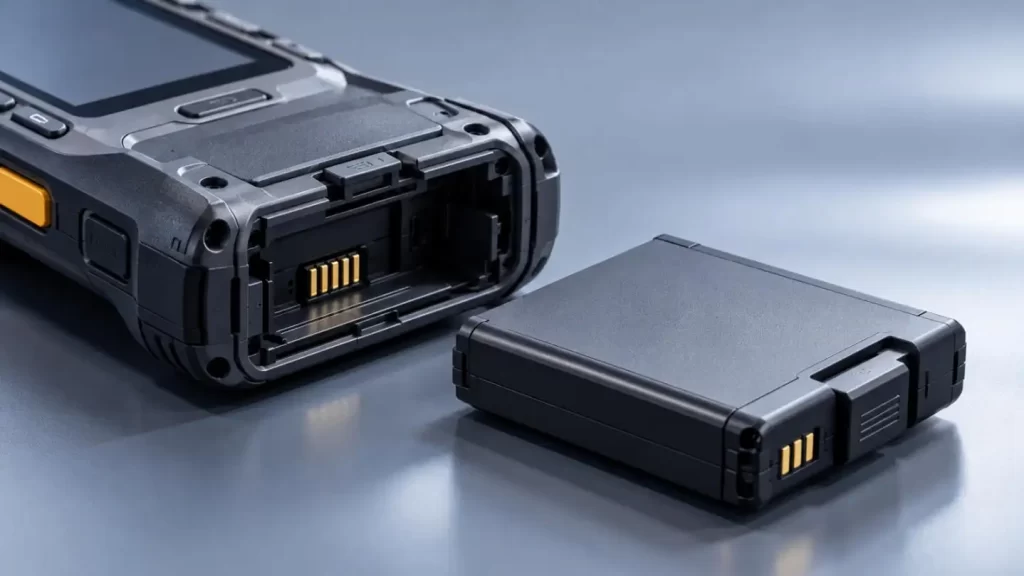
How Tolerance Stack-Up Determines Battery Fit
Understanding Worst-Case Assembly Clearance
A Replaceable Battery for Handheld Devices involves multiple mating features. Their dimensional variations accumulate rather than acting independently.
For a simplified rigid, one-dimensional fit:
• Minimum Clearance = Minimum Compartment Size − Maximum Battery Size
• Maximum Clearance = Maximum Compartment Size − Minimum Battery Size
Consider a hypothetical battery assembly:
| Parameter | Dimension |
| Battery compartment width | 80.0 ± 0.2 mm |
| Battery enclosure width | 79.6 ± 0.2 mm |
| Nominal clearance | 0.4 mm |
| Worst-case minimum clearance | 0 mm |
| Worst-case maximum clearance | 0.8 mm |
Despite a nominal clearance of 0.4 mm, extreme dimensional combinations produce either zero clearance or substantial movement.
Zero clearance may cause binding, particularly after thermal expansion. Excessive clearance allows vibration-induced displacement and unstable contact engagement.
This is an initial screening method. Plastic deformation, warpage, and assembly constraints require further evaluation.
Importance of GD&T Beyond Dimensions
Geometric Dimensioning and Tolerancing (GD&T) adds a level of control over functional relationships, as in:
• Position tolerances: Controls connector alignment to locating features.
• Straightness, flatness: Control guide-rail geometry and mating surfaces.
• Perpendicularity: Controls latch and contact engagement.
• Datum references: Establish a location for inspection/assembly which enables repeatability.
A battery might satisfy length and width tolerances but fail in functional assembly due to incorrect positioning of the locating features.
Critical Mechanical Interfaces in Replaceable Battery Design
For a Replaceable Battery for Handheld Devices, tolerance allocation should follow mechanical function rather than applying unnecessarily tight limits to every surface.
| Interface | Critical Parameter | Failure Risk |
| Battery enclosure | Dimensional envelope, warpage | Binding or excessive movement |
| Guide rails | Profile, alignment, clearance | Jamming or uneven insertion |
| Locking mechanism | Engagement depth, retention force | Accidental release |
| Spring contacts | Position, compression travel | Intermittent connection |
| Sealing gasket | Compression gap, surface flatness | Reduced IP protection |
Guide Rails and Locking Mechanisms
Structures that slide in require enough space to easily move in and out, while also allowing for lateral positioning to be controlled.
Latch engagement has to account for the clearance, deformation and wear of the materials to prevent unintended battery release.
When considering the above, other factors like wearing down guide rails, retention of the latch after repeated cycling, and mechanical keying against reverse installation need to be considered.
Spring contacts provide axial compliance. However, other factors like the thickness of the material and use environment impact contact resistance.
Blade connectors offer greater current-carrying capability compared to spring contacts.
Neither design is superior to the other based on the environment they are used in.
Manufacturing Precision: From Prototype to Production
Injection Molding and Dimensional Stability
Electrical contacts need to account for variation in position.
• Spring contacts provide axial compliance for a defined working stroke.
• Contact resistance and environmental factors impact spring contacts.
• Blade connectors provide greater current carrying capability compared to spring contacts.
• Neither design is superior based on the environment they are used in.
ISO 20457:2026 offers a method to define acceptance conditions and tolerances for molded plastic parts.
Tighter nominal tolerances do not automatically produce better assemblies. Critical-to-function dimensions require tighter process control, while nonfunctional surfaces can accept broader variation.
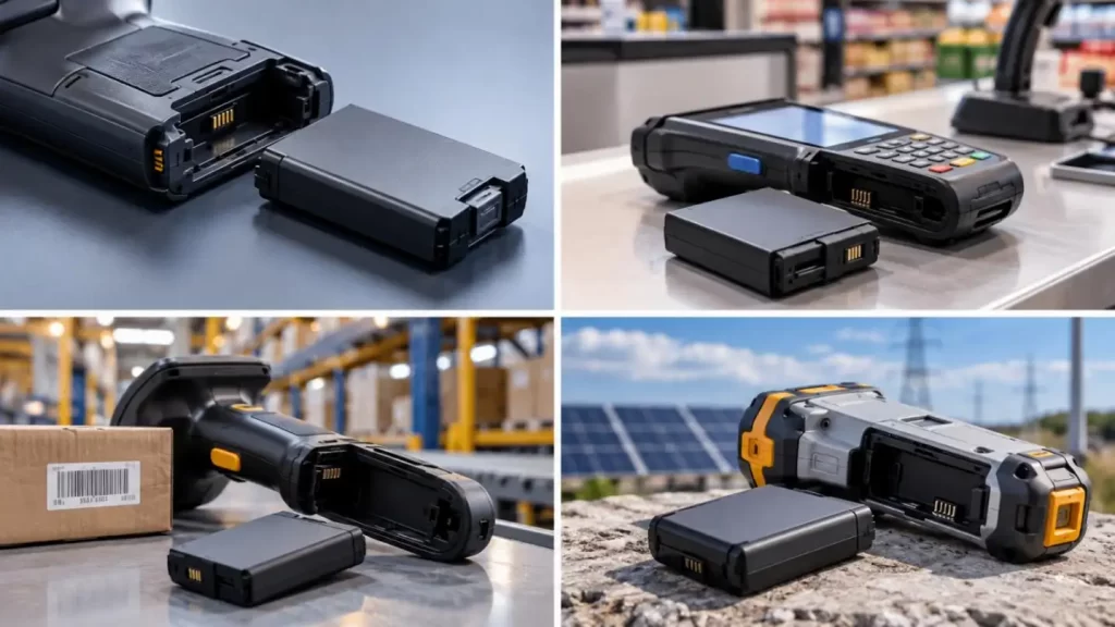
GLOFLUX Manufacturing and Dimensional Control
At GLOFLUX, we support custom battery dimensions, enclosure materials, mounting structures, connectors, and PCM/BMS integration.
Our manufacturing and dimensional references include:
| GLOFLUX Data | Engineering Relevance |
| 14 × 50 ± 0.5 mm rechargeable AA battery | Product-specific dimensional tolerance reference |
| Custom LiPo thickness down to 3 mm | Compact cell dimensional design capability |
| 60+ quality inspection checkpoints | Production quality-control framework |
| Prototype-to-mass-production OEM/ODM support | Design validation and production transition |
The AA specification does not establish a universal ±0.5 mm tolerance for custom battery housings. Project-specific tolerances must be confirmed against geometry, materials, tooling, and inspection capability.
How Mechanical Tolerances Affect Electrical Reliability
Replaceable Battery for Handheld Devices, particularly those using a Loose Fit design, can potentially experience Contact Bounce, Fretting Wear, and Increased Electrical Resistance.
Contact Heating:
P = I²R
At 5 A, the loss in the contact resistance increases from 10 mΩ to 50 mΩ and the loss in the contact resistance increases from 0.25 W to 1.25 W.
This excess heating promotes contact degradation and resistance increase, and voltage drops may cause device resets during peak current operation.
Thus, both the mechanical and the electrical design have to be assessed together.
• Contact Compression: Check if the contact force is above the minimum, and if travel is below the maximum.
• Current Loading: Consider both steady state and transient conditions.
• BMS (Battery Management System) Integration: Adjust BMS protection limits to account for system loss during maximum load conditions.
• Environmental Sealing: After a prescribed number of replacement cycles, verify that the gasket is compressed.
BMS protection cannot compensate for a physically unstable connection.
How to Validate Battery Fit Before Mass Production
For Replaceable Battery for Handheld Devices, Production Interchangeability is not guaranteed with prototype approval only.
Practical Validation may include:
- Measure the dimensions of critical features using calibrated gauges or coordinate measuring equipment.
- Assess the worst case combination of all features and clearances.
- Test batteries from different lots of production against each other.
- Assess loss of insertion and retention force of connectors and measure wear.
- Check vibration, drop, and temperature tests, and the performance of seals against the environment.
- Check for unexpected loss of Electrical Continuity.
Pilot Production should assess if dimensions are repeatable and if systems function as intended.
What OEM Buyers Should Specify
Before purchasing a Replaceable Battery for Handheld Devices, provide the following to the battery manufacturer:
• Battery compartment CAD drawings and critical GD&T
• Connector contact and allowable contact travel, insertion direction, removal force, expected replacement cycles
• Operating temperature, vibration, and IP
• Inspection criteria, batch traceability, safety documentation
UN 38.3 and IEC 62133-2, may provide assurance for the safety of the battery, and the transport of the battery respectively, but they do not replace application specific mechanical qualification.
Custom Replaceable Battery Engineering with GLOFLUX
GLOFLUX specializes in the integration of mechanical and electrical interfaces, along with battery management systems (BMS), to meet both the electrical and mechanical requirements of the battery subsystem.
Our engineers can assess your dimensional and connector constraints as well as your prototyping requirements for your next batch of replacement batteries.
To learn more, contact us to review your device drawings and discuss how we can design a custom battery tailored to your assembly and operating requirements.
FAQs
Q1: Can GLOFLUX customize replaceable battery dimensions for handheld devices?
Yes. GLOFLUX offers custom battery dimensions, enclosure shapes, mounting structures, and connector layouts based on device requirements.
Q2: Can GLOFLUX design slide-in battery housings and locking mechanisms?
Yes. GLOFLUX supports custom enclosures, guide rails, locking structures, and mechanical interfaces for replaceable battery packs.
Q3: What dimensional tolerances can GLOFLUX achieve?
Tolerance capability depends on the enclosure material, geometry, tooling, and manufacturing process. Project-specific tolerances require engineering confirmation.
Q4: What battery connectors can GLOFLUX customize?
GLOFLUX supports spring contacts, connector pins, wiring configurations, and device-specific electrical interfaces.
Q5: Does GLOFLUX provide customized BMS protection?
Yes. GLOFLUX offers PCM/BMS solutions with overcharge, over-discharge, overcurrent, short-circuit, and optional communication functions.
Talk to the Manufacturer
Resources & Insights
High Capacity Lithium Battery for Wearables: High-Voltage LiPo Cell Design
2026-10-19
Cylindrical Battery Packs for Laptops: 2S vs 3S vs 4S Battery Design
2026-10-19
Stage Lighting Battery Pack: Prevent Voltage Drop & LED Flicker
2026-10-19

Best Rechargeable Batteries for Smart Devices: Performance, Safety, and Selection Guide
2026-10-19


